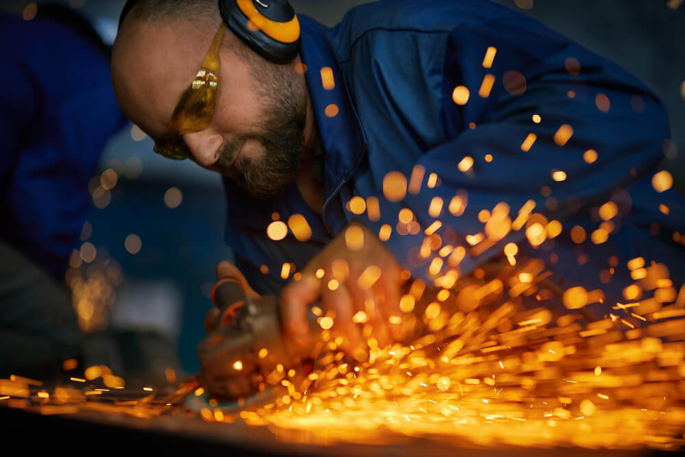

Welding inspection is the structured process that proves a welded joint meets the strength, soundness and dimensional requirements of a construction code before it enters service. It combines direct examination of the weld, non-destructive testing matched to the likely defect type, and a documented chain that qualifies both the procedure and the welder.
No single inspection guarantees a sound weld. Quality is assured by a chain: a qualified procedure tells the welder how to make the joint, a qualified welder proves they can follow it, visual inspection confirms the finished bead, and non-destructive testing (NDT) looks below the surface. Each link catches problems the others miss.
A radiograph will not flag the wrong preheat, and a procedure record will not catch a lack of fusion buried in a root pass. The inspector's job is to make sure every link is present and documented.
Visual testing (VT) is the oldest, cheapest and most productive method, and code requires it on effectively every weld. It is applied in three phases:
VT tools are simple: adequate light, a weld gauge for throat and leg size, and a welding profile gauge. Many surface-breaking flaws are first suspected by eye.
When a flaw breaks or nearly breaks the surface, surface NDT is the right tool. Liquid penetrant testing (PT) works on any non-porous material: dye is drawn into an open discontinuity by capillary action, excess is removed, and a developer pulls the dye back out to form a visible indication.
Magnetic particle testing (MT) is faster and also finds slightly subsurface flaws, but only on ferromagnetic steels, because it relies on flux leakage at a discontinuity to gather iron particles. Choose PT for austenitic stainless and aluminium; choose MT for carbon and low-alloy steel where it is applicable.
Both are covered in more depth in our guides to liquid penetrant testing and the broader family of weld defects .
Buried, three-dimensional flaws such as slag, porosity, incomplete penetration and internal cracks need volumetric methods. Radiographic testing (RT) passes X-rays or gamma rays through the joint onto film or a digital detector, giving a permanent image that is excellent for volumetric flaws but weaker at tight planar cracks aligned across the beam. Ultrasonic testing (UT), including modern phased-array, sends high-frequency sound into the metal and times the echoes; it excels at planar defects such as lack of fusion and cracks, and needs no radiation exclusion zone. Many codes now accept UT in place of RT for thicker sections. See our detailed treatment of radiographic testing.
| Method | Abbrev. | Flaw type found | Main limitation |
|---|---|---|---|
| Visual | VT | Surface cracks, undercut, profile, size | Surface only |
| Liquid penetrant | PT | Surface-breaking flaws, any material | Open to surface only |
| Magnetic particle | MT | Surface and near-surface flaws | Ferromagnetic metals only |
| Radiography | RT | Volumetric: porosity, slag, incomplete penetration | Poor at tight planar cracks; radiation |
| Ultrasonics | UT | Planar: lack of fusion, cracks; volumetric sizing | Operator skill; coupling and access |
Documentation is what turns a good-looking weld into an accepted one. Three records form the core, under ASME Section IX or ISO 15614 and ISO 9606:
A WPS qualified by testing that has no supporting PQR, or an expired welder qualification, is a valid reason to reject production welds regardless of how they test. The exceptions are procedures the code already accepts without a PQR: prequalified WPSs under AWS D1.1, and AWS standard welding procedure specifications adopted under ASME Section IX Article V with the required demonstration weld.
Whether an indication is acceptable is never the inspector's opinion; it is set by the governing construction code. AWS D1.1 covers structural steel, ASME B31.3 process piping, the ASME Boiler and Pressure Vessel Code pressure equipment, and ISO 5817 defines quality levels B, C and D for imperfections.
The code fixes limits for undercut depth, porosity size and distribution, crack tolerance (usually zero) and required NDT extent. NDT techniques themselves follow method standards such as ASME Section V or the ISO 17636, 17638, 17640 and 3452 series, while personnel are certified to ASNT SNT-TC-1A or ISO 9712.
A certified welding inspector, such as an AWS CWI, a CSWIP welding inspector or an IIW International Welding Inspector (IWI), working alongside NDT technicians certified to ISO 9712, ties the chain together. They verify base metal and consumables on receipt, witness fit-up and preheat, monitor production, review NDT reports against the code, and sign off or reject.
Their records become the traceable evidence that a joint is fit for service. Keeping that evidence organized and linked to each asset is where a CMMS helps maintenance teams connect fabrication records with later inspection history. Book a Fabrico demo to see how it works on your assets.
Visual testing is only as good as the conditions it is done in. ISO 17637 asks for at least 350 lux of white light at the surface, with 500 lux recommended. For direct inspection the inspector's eye should be within 600 mm of the surface, at an angle of not less than 30 degrees. Where access is worse than that, use mirrors, borescopes or cameras and note it in the report.
Acceptance limits change between editions, so the inspection plan should state which edition applies. For structural steel under AWS, the current edition is AWS D1.1/D1.1M:2025, which superseded the 2020 edition. A contract can call up an earlier edition, and the inspector works to the edition the contract specifies.
A useful record ties each weld to its evidence:
With that on file against the asset, a defect found years later can be traced to the procedure, the welder and the inspection that cleared it.
The WPS is the forward-looking instruction that tells a welder how to make a joint within allowed parameter ranges. The PQR is the backward-looking evidence: the exact values used on a qualification coupon and the destructive test results that prove those parameters produce sound, strong metal. A WPS qualified by testing is supported by one or more PQRs; a prequalified AWS D1.1 WPS needs none.
Prefer UT for thicker sections and for planar defects such as lack of fusion and cracks, which radiography can miss when they lie across the beam. RT remains strong for volumetric flaws like porosity and slag and gives a permanent image. UT also avoids a radiation exclusion zone, which suits occupied sites.
Yes. Codes require visual inspection on essentially every weld, and it is applied before, during and after welding. Many defects, including wrong preheat, poor fit-up and surface profile problems, are only catchable visually and are cheapest to correct before they are welded over.
The governing construction code, for example AWS D1.1, ASME B31.3, the ASME BPVC or ISO 5817, sets the pass or fail limits. The inspector applies those limits; they do not invent them, so the correct code and edition must be identified at the outset.





















Programați o întâlnire individuală cu experții noștri sau înscrieți-vă direct în planul nostru gratuit.
Nu este nevoie de card de credit!






 Login
Login
 Blog
Blog