Key takeaways
Short answer: A reliability block diagram (RBD) models how component reliability combines into system reliability. Components in series multiply (much lower system reliability); components in parallel add coverage (much higher). RBD evaluation before redundancy investments reveals whether the math justifies the spend. Most plants make redundancy decisions without RBD and overpay or under-invest based on intuition. See also The Reliability Engineer Role.
A diagram showing system components arranged in series, parallel, or combination. Each component has a known reliability (probability of working over a time period).
The diagram computes system reliability from the component reliabilities.
If component A and component B are in series (both must work):
R(system) = R(A) x R(B)
Two components at 95% reliability in series produce a 90.25% system reliability. Series multiplies penalty.
If component A and component B are in parallel (only one needs to work):
R(system) = 1 - (1 - R(A)) x (1 - R(B))
Two components at 95% reliability in parallel produce a 99.75% system reliability. Parallel multiplies coverage.
Three plants are considering redundancy:
Plant A: 95% reliable pump, considering second pump. RBD says new reliability is 99.75%. Solid investment for critical service.
Plant B: 99.5% reliable controller, considering redundant controller. RBD says new reliability is 99.9975%. Marginal investment; the original was already very reliable.
Plant C: 90% reliable line with 5 series stations. Adding redundancy on one station improves it from 90% to 99% but the line is still 81% (after series penalty). Need to address all stations, not just one.
RBD reveals each case clearly. Without it, redundancy decisions are by intuition.
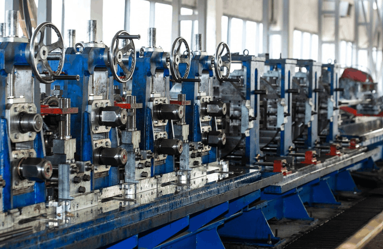
1. Series-dominant systems. Discrete production lines where every station is required. Reliability drops fast as series count grows. Improvement requires raising every component or adding parallel.
2. Parallel-dominant systems. Power systems with redundant supply, network with redundant paths. Tolerate component failures well.
3. Mixed. Most real systems. Some segments parallel, some series.
RBD makes this calculation defensible.
1. Adding redundancy to non-bottleneck components. Doubling the most reliable component does little.
2. Assuming independence. Components share failure modes (common power supply, common cooling) that defeat parallel redundancy.
3. Static reliability assumption. Component reliability degrades with age; assume worst-case for long-term decisions.
4. Ignoring switchover time. Active redundancy provides immediate switchover; passive redundancy has a delay during which the system is down.
For these cases, RBD is a starting point, not the final answer.
OEE Availability degrades with low system reliability. RBD evaluation of asset architecture supports targeted reliability improvement to lift OEE Availability.
A modern CMMS captures component reliability from work order history, supports RBD modeling at the asset hierarchy level, and evaluates redundancy options against actual failure data.
Fabrico's CMMS captures component reliability from work order history and supports RBD-style analysis for redundancy decisions.
See how Fabrico captures this automatically — explore OEE for manufacturing or book a demo.
Historical MTBF data from your CMMS; OEM specs; industry databases (OREDA for oil and gas, others by industry).
Small systems can be done in a spreadsheet. Complex multi-component systems benefit from RBD software.
FTA is more general and handles common cause failures. RBD is simpler and faster for clear series/parallel structures.
As accurate as the underlying data. Historical data on similar service is most reliable.
No. Apply to systems where redundancy decisions or major reliability investments are being considered.