Key takeaways
MIG and MAG welders fail in predictable ways: the wire stops feeding, the weld fills with pores, or the arc turns harsh. This guide gives maintenance technicians and plant engineers the ordered causes and first checks for each fault family, manual or robotic.
A MIG machine presents open circuit voltage (OCV) at the torch whenever the trigger circuit is live, and higher voltages inside the cabinet. Disconnect and lock out before opening it, and treat capacitors as stored energy after power-off.
| Symptom | Most likely cause | First check |
|---|---|---|
| Wire birdnests at drive rolls | Blocked liner or tip, roll tension too high | Release rolls, pull wire by hand, feel for drag |
| Wire burns back into tip | Wire speed too low for voltage, worn or wrong-size tip | Verify tip size, reset to procedure settings |
| Wire slips, erratic feed | Worn or wrong-groove rolls, low tension | Check groove size and type against the wire |
| Porosity in the weld | Lost shielding gas, contaminated metal | Cylinder, flow, leaks, drafts, spattered nozzle |
| Unstable, wandering arc | Worn contact tip, poor work lead | Swap tip, clamp to clean bare metal |
| Excess spatter | Voltage and wire speed mismatch, gas mix, worn consumables | Reset to known-good settings, inspect tip and nozzle |
| Machine cuts out mid-weld | Duty cycle exceeded, blocked airflow, failed fan | Let it cool, check vents and fan |
Feed faults show up as birdnesting (wire tangling at the drive rolls), burnback (the arc melting wire into the contact tip), or stubbing. The feed path is a chain: spool brake, rolls, liner, tip. A restriction anywhere downstream makes the rolls push wire sideways into a tangle.
Repeated burnback points to wire speed too low for the voltage, the tip too close to the work, or a worn tip.
Porosity means the weld pool lost its protection. Work the gas path from cylinder to nozzle, then look at the metal.
An erratic, wandering, or harsh arc has three usual suspects, in order:
If the machine welds fine and then cuts out, suspect duty cycle first: a 60 percent rating means six minutes of arc time in every ten. Trips well below the rating point to blocked airflow or a failed cooling fan. If the fan never starts, the fault may be on the control side; apply the same discipline as with contactor and motor starter failures and find the physical cause instead of just resetting. Indicator meanings vary by model, so confirm them in the manual.
Excess spatter usually means a voltage and wire speed mismatch, the gas mix (higher CO2 runs with more spatter than argon-rich blends), or worn consumables. Burn-through and lack of fusion are parameter and fit-up fundamentals: triage settings versus consumables versus technique, and involve your welding engineer before rewriting a qualified procedure.
Tips, nozzles, liners, and drive rolls are wear parts with service lives. Run-to-failure is a bad strategy because the consequence is a stopped line. Robotic cells should replace consumables on schedule, not on failure: a burned-back tip mid-shift stops the cell and everything downstream.
Build these intervals into a written preventive maintenance schedule instead of relying on operator memory.
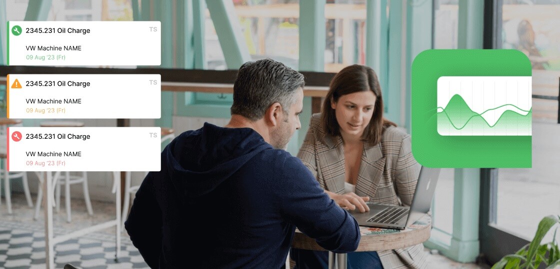
Every fault above is a downtime event. Log each one with a cause code (liner, tip, gas, work lead, duty cycle) and track MTBF and MTTR per welder or cell. Patterns surface fast: one feeder eats liners, one cell trips on heat every afternoon.
On robots, existing arc-monitoring signals plus downtime logging identify which consumable or parameter drift causes the most stops: exactly the job of OEE tracking on welding lines. Chronic offenders get a structured root cause analysis and a permanent fix, and the losses show up truthfully in your OEE numbers instead of hiding as stops nobody logged.
Fabrico is computer-vision-verified OEE plus closed-loop maintenance execution: cameras catch stops and micro-stops that manual logs and sensors miss, and maintenance work orders close the loop from detection to fix. On a welding line, the short stops from a dying liner get counted, coded, and scheduled for a fix instead of vanishing between shifts. See it on your line: book a Fabrico demo.
Something downstream is restricting the wire while the rolls keep pushing: usually a clogged liner or blocked tip. Pull the wire through by hand to find the drag, swap the tip, and clean or replace the liner.
Lost shielding gas or dirty base metal. Check the cylinder, flow setting, line leaks, drafts, and a spatter-clogged nozzle first, then look for oil, paint, rust, or moisture on the joint.
There is no universal interval: it depends on wire type, arc-on time, and cell cleanliness. Set a starting interval, then tune it with your downtime records. Robots should replace on schedule, not at failure.
Usually the thermal protection is working: duty cycle exceeded, airflow blocked, or fan failed. Let it cool, clear the vents, and verify the fan runs. Check the manual for indicator meanings, and disconnect and lock out before opening the cabinet.