


 Login
 Blog

PowerFlex 525 Fault Codes: What They Mean and How to Fix Them

When an Allen-Bradley PowerFlex 525 trips, it shows an F followed by a number and the driven machine stops. This guide covers the PowerFlex 525 fault codes a maintenance team meets most often, what each one means, the usual cause, and how to clear it, so you can get from a stopped line to a root cause in minutes.
Key takeaways
- The trips you will see most are F004 Undervoltage, F005 Overvoltage, F007 Motor Overload, F008 Heatsink Overtemp and F013 Ground Fault.
- The code is a diagnosis, not the disease. The real problem is almost always in the supply, the load, the wiring, or the cooling, not the drive itself.
- A drive that faults again and again is a maintenance signal. Logging which fault recurs on which asset turns a nuisance trip into a pattern you can fix for good. Every one of those trips is unplanned downtime, and the pattern only appears once each is counted.
How a PowerFlex 525 fault works
The PowerFlex 525 protects itself and the motor by tripping the moment a measured value leaves its safe window: DC bus voltage, output current, heatsink temperature, or a lost signal. The display shows the fault code, for example F005, and the drive coasts to a stop.
Read the code as a pointer, not a verdict. F005 Overvoltage does not mean the drive is broken. It means the DC bus climbed too high, usually because a high-inertia load decelerated faster than the drive could absorb the energy the motor pushed back.
PowerFlex 525 fault code reference
The faults most common on the shop floor, with the code as it appears on the display, the fault name, and the usual cause. The complete list lives in Rockwell publication 520-UM001; this is the working subset.
| Code | Fault | Usual cause |
|---|---|---|
| F002 | Auxiliary Input | A wired external trip or interlock opened |
| F003 | Power Loss | Incoming AC line lost or running on a single phase |
| F004 | Undervoltage | DC bus fell below minimum (supply dip or interruption) |
| F005 | Overvoltage | DC bus rose above maximum (fast decel of a high-inertia load, or a line surge) |
| F006 | Motor Stalled | The drive could not accelerate or decelerate the motor |
| F007 | Motor Overload | The motor drew more current than its overload setting allows |
| F008 | Heatsink Overtemp | The power module ran too hot |
| F009 | Control Module Overtemp | The control electronics ran too hot |
| F012 | HW Overcurrent | Output current exceeded the hardware limit |
| F013 | Ground Fault | A current path to earth at the drive output |
| F015 | Load Loss | Output torque current dropped below the set threshold (broken coupling or lost load) |
| F021 | Output Phase Loss | One output phase to the motor is missing |
| F029 | Analog Input Loss | A configured analog signal was lost |
| F033 | Auto Restart Tries | The drive used up its programmed automatic restart attempts |
| F038 to F040 | Phase U, V or W to Gnd | A phase to ground fault between the drive and the motor on that phase |
| F048 | Params Defaulted | Parameters were reset to factory defaults |
| F059 | Safety Open | The Safe Torque Off inputs are not enabled |
| F064 | Drive Overload | The drive rating was exceeded |
| F070 | Power Unit | A failure in the drive power section |
| F071 | DSI Net Loss | Modbus or DSI communication was interrupted |
| F073 | EtherNet/IP Loss | The embedded network adapter lost its connection |
Fixing the faults you will actually see
F005 Overvoltage. The DC bus went over its limit. On a real line this is almost always a deceleration problem: a loaded conveyor or a high-inertia fan is being told to stop faster than the drive can bleed off the returned energy.
Extend the decel time, or fit a dynamic braking resistor sized for the load. Rule out AC line surges and a high or floating supply voltage before you suspect the drive.
F004 Undervoltage. The bus dropped too low. Look upstream, not at the drive: a sagging supply, a loose incoming terminal, or a shared feed with a large motor or welder that pulls the line down on start. Confirm the input voltage under load.
F007 Motor Overload. The motor pulled more current than its overload allows, for too long. Check the mechanical load first (a jam, a seized bearing, a load that grew), then confirm the motor overload current parameter P033 matches the motor nameplate and that the boost is not set too high.
F008 Heatsink Overtemp. The power module overheated. Clean the heatsink and check the cooling fan, the enclosure ventilation, and the ambient temperature. A drive in a sealed panel next to a heat source will trip on a hot afternoon even when nothing electrical is wrong.
Before you touch the drive output or the motor leads: remove power and lock out the drive, wait three minutes, then measure across the DC+ and DC- terminals until the bus reads zero volts. Rockwell also says to verify that the line terminals are dead and to keep the meter on the terminals until the voltage has discharged to zero.
F013 Ground Fault. The drive found current leaking to earth at its output. This is a wiring and insulation fault, and it is a safety issue.
With the drive locked out and the bus at zero volts, disconnect the motor leads from T1, T2 and T3 and megger the motor and the motor cable from there, never through the drive, then inspect the gland and terminations for damage or moisture, and repair the grounded conductor before you run again.
A ground fault that keeps returning on the same motor points to failing winding insulation, which is a job for planned replacement, not repeated resets.
F029 Analog Input Loss and F033 Auto Restart Tries. F029 means a speed or setpoint signal the drive was told to watch has disappeared: check the analog wiring and the loss-of-signal parameter. F033 means the drive already tried to restart itself the set number of times and gave up, so the real fault (often F004 or F005) is still present. Fix the first fault, and F033 stops.
F059 Safety Open and F071 or F073 network loss. F059 means the Safe Torque Off inputs are not made: check the safety circuit and the wired safety device or jumpers. F071 and F073 are communication drops on Modbus or DSI and on EtherNet/IP: check the cable, the connector, the node address, and the controller that talks to the drive.
How to clear a PowerFlex 525 fault
Do not clear a fault until you know why it tripped. Once you have the cause, reset the drive by pressing Esc to acknowledge the fault and then Stop (this clears it when P045 [Stop Mode] is set between 0 and 3), by setting A551 [Fault Clear] to 1, by a digital input programmed to 13 Clear Fault, by cycling input power, or over the network with a fault-clear command.
If the fault returns the instant you run, the condition is still there. Repeatedly clearing a ground fault or an overcurrent just to keep production moving is how a small problem becomes a burned motor or a damaged drive.
Turn recurring faults into a maintenance signal
One overvoltage trip is an event. The same drive tripping on F005 every Monday, or on F013 twice a month, is a pattern that predicts a failure. Teams that stay ahead of drive faults do not just clear them, they log them: which code, which asset, which shift, how often. That record is where a stopped machine becomes a scheduled fix instead of a surprise.
This is what a CMMS and predictive maintenance software are for: capturing every trip against the asset, surfacing the drives that fault most, and planning a follow-up task before the next one stops the line. If VFD faults are turning into unplanned downtime, read how Fabrico tracks downtime and how the recurring ones get caught early.
Related reading: Yaskawa VFD fault codes and motor insulation classes, where the F013 ground-fault story usually ends.
PowerFlex 4 F5 and PowerFlex 525 F005: the same fault
If your drive is a PowerFlex 4, its manual lists this fault as F5 OverVoltage, and it means exactly the same thing: the DC bus voltage exceeded its maximum value. The PowerFlex 523 and 525 share one manual, 520-UM001, where it appears as F005. A few codes in that manual do not apply to the 523, including F015 Load Loss, F059 Safety Open and F073 EN Net Loss.
The parameter numbers differ between the two families:
- Decel time: P040 [Decel Time 1] on a PowerFlex 4, P042 [Decel Time 1] on a 525.
- Stop mode: P037 [Stop Mode] on a PowerFlex 4, P045 [Stop Mode] on a 525.
- Fault clear: A100 [Fault Clear] on a PowerFlex 4, A551 [Fault Clear] on a 525.
- Bus regulator: A117 [Bus Reg Mode] on a PowerFlex 4, A550 [Bus Reg Enable] on a 525.
F5 and F005 fix checklist
- Lengthen the decel time (P042 on a 525, P040 on a PowerFlex 4).
- Confirm the bus regulator is enabled (A550 on a 525, A117 on a PowerFlex 4). Both are enabled by default.
- Check the AC line for high voltage or transients. Rockwell lists both as causes alongside motor regeneration.
- If the load really must stop that fast, fit a dynamic brake resistor and select it in A437 [DB Resistor Sel] on a 525. The A550 description in 520-UM001 explains how the two settings interact.
- On a PowerFlex 4, check P036 [Start Source]. The drive can trip F5 if it is set to 2-W Hi Speed and a coast to stop command arrives while the drive is running.
Clearing faults and auto restart
Press Esc to acknowledge the fault. On a PowerFlex 4 the latest fault is in d007 [Fault 1 Code]. Fix the cause, then clear the fault with Stop (if the stop mode parameter is set between 0 and 3), with the fault clear parameter, with a digital input set to Clear Fault, or by cycling power.
For unattended sites, auto restart can clear a Type 1 fault and restart the drive: set A541 [Auto Rstrt Tries] and A542 [Auto Rstrt Delay] on a 525, or A092 and A093 on a PowerFlex 4. With the delay set to 0, the drive clears an overvoltage, undervoltage or heatsink overtemperature fault without restarting.
Rockwell warns to use caution, because the drive then issues its own start command. When the tries run out, the drive trips F033 Auto Restart Tries, which tells you the original fault is still there.
PowerFlex 4, 4M, 40 and 40P fault codes
The older PowerFlex 4, 4M, 40 and 40P drives use a different code list from the PowerFlex 525. When the drive trips, the display flashes the fault number and the red FAULT indicator flashes. Rockwell prints the codes as F plus a number, for example F7 or F81.
Fault 007 or F7? F7 is Motor Overload. But the last three faults are stored in parameters d007, d008 and d009, with d007 holding the most recent one, so a report of "fault 007" can also mean someone is reading parameter d007. Check which one you are looking at before you act. On the PowerFlex 40P the fault queue is b007 to b009.
| Code | Name | What it means |
|---|---|---|
| F2 | Auxiliary Input | The auxiliary input interlock is open. |
| F3 | Power Loss | PowerFlex 4 and 40P: the DC bus voltage stayed below 85% of nominal (the 40P also trips on single phase operation). PowerFlex 4M and 40: excessive ripple on the DC bus voltage. |
| F4 | UnderVoltage | The DC bus voltage fell below the drive's minimum value. |
| F5 | OverVoltage | The DC bus voltage exceeded the drive's maximum value. |
| F6 | Motor Stalled | The drive is unable to accelerate the motor: it sits in current limit instead of reaching speed. |
| F7 | Motor Overload | The drive's internal electronic motor overload has tripped. |
| F8 | Heatsink OvrTmp | The heatsink temperature has gone above a preset limit. |
| F12 | HW OverCurrent | The drive output current has exceeded the hardware current limit. |
| F13 | Ground Fault | The drive detected a current path to earth ground at one or more of its output terminals. |
| F29 | Analog Input Loss | (PowerFlex 40 and 40P) An analog input is set to fault on signal loss and the signal was lost. |
| F33 | Auto Rstrt Tries | The drive tried to reset a fault and resume running for the programmed number of A092 [Auto Rstrt Tries] (A451 on the 4M) and did not succeed. |
| F38 | Phase U to Gnd | A phase to ground fault was detected between the drive and the motor in phase U. |
| F39 | Phase V to Gnd | A phase to ground fault was detected between the drive and the motor in phase V. |
| F40 | Phase W to Gnd | A phase to ground fault was detected between the drive and the motor in phase W. |
| F41 | Phase UV Short | Excessive current was detected between output terminals U and V. |
| F42 | Phase UW Short | Excessive current was detected between output terminals U and W. |
| F43 | Phase VW Short | Excessive current was detected between output terminals V and W. |
| F48 | Params Defaulted | The drive was commanded to write default values to its EEPROM, so all parameters are back at factory settings. |
| F63 | SW OverCurrent | Output current went above the programmed A098 [SW Current Trip] level (A448 on the 4M). |
| F64 | Drive Overload | The drive's own rating of 150% for 1 minute or 200% for 3 seconds has been exceeded. |
| F70 | Power Unit | The drive detected a failure in its power section. |
| F71 | Net Loss | The communication network has faulted. |
| F80 | SVC Autotune | (PowerFlex 40 and 40P) The autotune function was cancelled by the user or failed. |
| F81 | Comm Loss | The RS-485 (DSI) port stopped communicating, for example with a remote HIM, a network adapter or an RS-485 master. |
| F91 | Encoder Loss | (PowerFlex 40P only) One of the two encoder channel signals is missing. |
| F100 | Parameter Checksum | The checksum read from the board does not match the checksum the drive calculated, so the stored parameters cannot be trusted. |
| F111 | Enable Hardware | (PowerFlex 40P only) PowerFlex 40P hardware enable or DriveGuard Safe-Off fault. |
| F122 | I/O Board Fail | The drive detected a failure in its control and I/O section. |
Clearing a fault: correct the cause first, then press Stop (when P037 [Stop Mode] is set to 0 to 3; P107 on the 4M), cycle drive power, set A100 [Fault Clear] to 1 (A450 on the 4M), or use a digital input set to Clear Fault. On the 40P, press and hold the Up Arrow for three seconds. Type 1 faults can reset and restart by themselves when A092 [Auto Rstrt Tries] is above 0; Type 2 faults never reset automatically.
Safety: before working on the drive, Rockwell's PowerFlex 4, 40 and 40P manuals say to isolate the mains supply and wait three minutes for the bus capacitors to discharge; the PowerFlex 40 and 4M manuals add to measure the DC bus voltage at the DC+ and DC- terminals, which must be zero. A dark display does not mean the capacitors are discharged.
Source: Rockwell Automation user manuals for the PowerFlex 4 (22A-UM001), PowerFlex 4M (22F-UM001), PowerFlex 40 (22B-UM001) and PowerFlex 40P (22D-UM001), troubleshooting chapters.
Frequently asked questions
What is the most common PowerFlex 525 fault? On most lines it is F005 Overvoltage or F004 Undervoltage, both supply and deceleration issues, followed by F007 Motor Overload. F008 Heatsink Overtemp climbs in summer.
How do I reset a PowerFlex 525 fault? Press Esc, then Stop (with P045 [Stop Mode] set between 0 and 3), set A551 [Fault Clear] to 1, cycle input power, or send a fault-clear over the network. Find and fix the cause first, or it trips again.
Does a fault code mean the drive is broken? Usually not. Most PowerFlex 525 faults point to the supply, the load, the wiring, or the cooling. A true drive-hardware fault such as F070 Power Unit is the exception, not the rule.
Where is the full fault list? Rockwell publication 520-UM001, the PowerFlex 525 user manual, lists every code and the detailed condition behind it.
Fabrico is a cloud-based MES and OEE platform for manufacturers, with computer-vision-verified OEE monitoring, PLC connectivity and maintenance management (CMMS) built in.
Stop chasing this fault by hand. Fabrico logs stops on connected machines against each machine's history, so a repeating fault shows up before it becomes a hard line stop, and the team can open a prioritized work order with the stop itself captured on video wherever a camera covers the line.
Fabrico is software for OEE, downtime tracking and maintenance. We do not sell parts or repair services.
Related articles











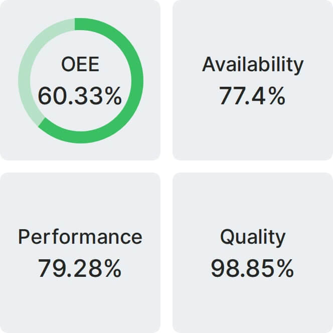
Real Fabrico tiles, sample data.