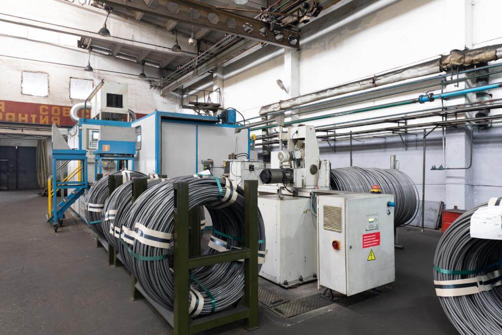

Cable fault location is the two-stage discipline of finding a fault in an underground power cable: first narrowing it to a short section along the route (pre-location), then marking the exact spot for excavation (pinpointing). Underground cables cannot be inspected visually, so the workflow relies on measurements from the cable ends, then walking the route with a receiver.
Distance measurements from a cable end are accurate to within a few percent of the length, which on a long feeder can still mean tens of metres of trench, far too coarse to open the road once.
Pre-location narrows the fault to the right manhole or section; pinpointing then resolves it to within roughly a metre using surface detection. Skip either stage and you waste a day or dig on a flawed estimate.
The correct method depends entirely on the fault, so insulation-resistance and continuity tests at the outset tell you what you are dealing with before you choose a technique.
These simple checks classify the fault and steer the whole job. For a refresher on the insulation side, see our note on motor insulation classes.
A TDR, or cable radar, injects a low-voltage pulse and times the reflections. It converts the round-trip time to distance using the cable velocity of propagation (VOP), commonly around half the speed of light for power cables. An open circuit reflects the pulse with the same polarity; a short or low-resistance fault reflects it inverted.
TDR is fast and non-destructive but cannot see a high-resistance fault on its own, because a small pulse will not break down the insulation to create a reflection.
Most in-service faults are high-resistance, so two high-voltage techniques dominate:
The Murray loop bridge, a Wheatstone-bridge resistance ratio, still helps when a healthy parallel conductor is available.
Safety first: surge and test voltages can kill. Before any high-voltage step, the cable must be switched out, isolated and grounded, the far end guarded or watched so no one can touch it, and the surge generator bonded to ground. After the last shot, and after every VLF or DC test, discharge the cable through the test set's discharge resistor and apply a solid ground before anyone touches a conductor, because a long cable holds a dangerous charge after the test set is switched off.
At the estimated spot, a surge generator, commonly called a thumper, discharges a high-voltage capacitor into the cable every few seconds. At the fault the discharge arcs across, producing a mechanical thump and an electromagnetic transient. The operator walks with two sensors:
Combining both signals resolves the fault to within about a metre. For jacket faults, an earth-gradient (step-voltage) survey traces the leakage current to the breach instead of listening for an arc.
| Fault type | Typical fault resistance | Pre-location method | Pinpointing method |
|---|---|---|---|
| Open circuit | Very high (broken conductor) | TDR (same-polarity reflection) | Surge or capacitive tracing |
| Short or low-resistance | Below a few hundred ohms | TDR (inverted reflection) | Thumper with acoustic microphone |
| High-resistance | Kilohms to megohms | Arc reflection or impulse current | Thumper with acoustic plus EM receiver |
| Intermittent or flashing | Variable, voltage dependent | Impulse current (ICE) method | Thumper with EM correlation |
| Sheath or jacket | Earth-leakage path | Murray or Glaser bridge, or voltage drop method | Earth-gradient step-voltage survey |
Locating the fault is half the job; you also need to know whether the rest of the cable is fit to re-energise. Two diagnostics are standard on medium-voltage cable:
These fit into a broader condition-monitoring routine; see our overview of partial discharge testing for the online side of cable diagnostics. Fabrico holds the test records, VLF and tan delta results, and repair history against each cable asset so trends stay visible. Book a Fabrico demo to see how the asset history fits together.
A TDR converts time to distance with d = (v x t) / 2, where v is the velocity of propagation set in the instrument and t is the round trip time of the pulse. The division by two is there because the pulse travels to the fault and back. Any error in v becomes the same percentage error in the distance, so a velocity that is 5 percent wrong puts the dig 5 percent of the fault distance off. Calibrate v on a healthy core of the same cable whose length you know, then test from both ends: the two distances to the fault should add up to the cable length. If they do not, the velocity or the route length is wrong.
A standard TDR pulse is too weak to break down a high-resistance fault, so it produces no reflection there. Arc reflection solves this by using a surge to ionise the fault into a temporary arc the TDR can then see.
The cable must be de-energised, isolated and earthed, with the surge energy matched to its rating. Too much thumping energy can enlarge the fault or damage sound insulation, so operators use the minimum that gives a clear signal.
Run them after a repair to prove the cable before re-energising, and periodically as condition monitoring. VLF provides a withstand or diagnostic voltage at 0.1 Hz, while tan delta grades dielectric loss to reveal ageing no single fault-location shot would catch.
Stop chasing this fault by hand. Fabrico logs each stop against the machine's history, so a repeating fault shows up before it becomes a hard line stop, and the team can open a prioritized work order with the stop itself captured on video wherever a camera covers the line.





















Programați o întâlnire individuală cu experții noștri sau înscrieți-vă direct în planul nostru gratuit.
Nu este nevoie de card de credit!






 Login
Login
 Blog
Blog