


 Login
 Blog

HMI Data Collection for OEE: What the HMI Holds, What to Read Instead

In short: HMI data collection for OEE works best when you read what the HMI shows at its source, usually the PLC behind the panel, read-only, and take the stop reason from the operator. The HMI is a window on the machine, not the place the data lives.
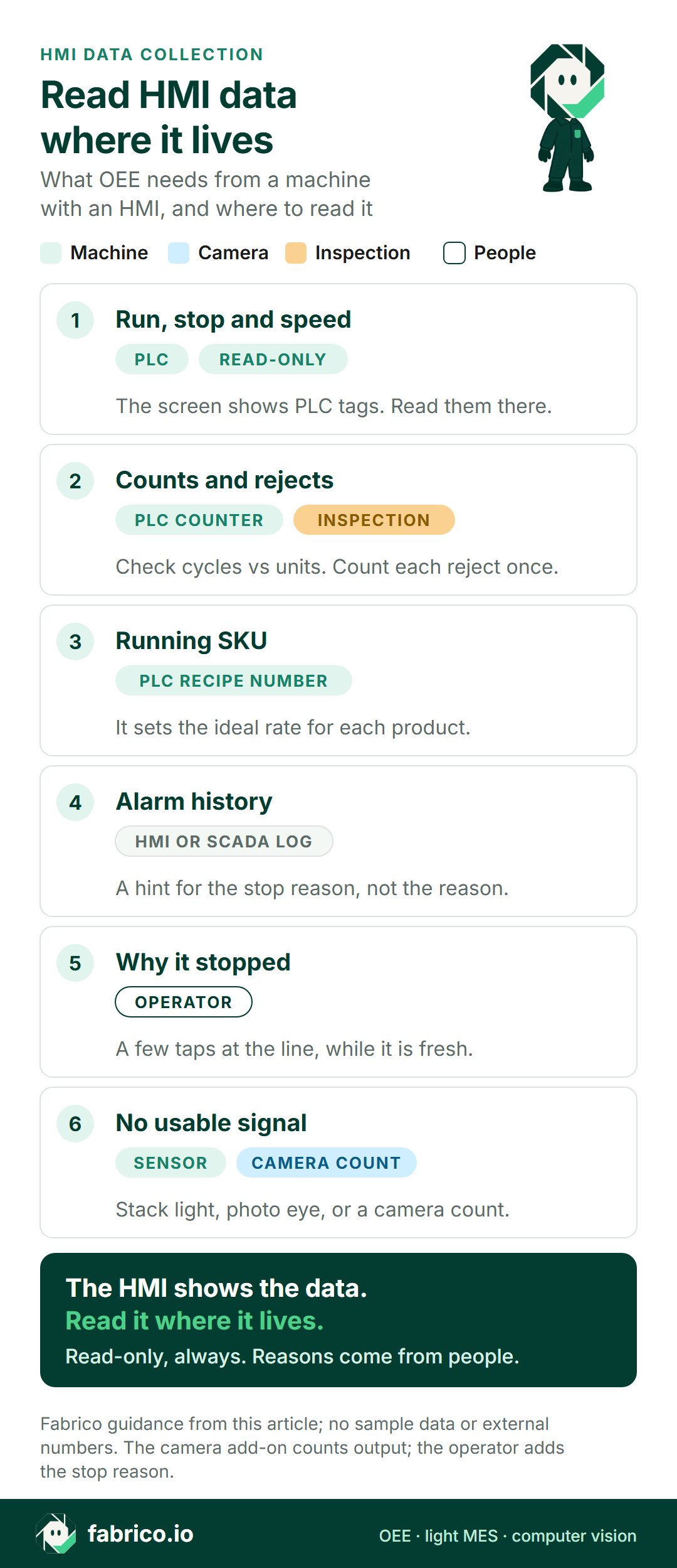
- Run state, counts, alarms and the recipe on an HMI screen are mostly PLC values. Read them once, read-only, from the PLC, or from a SCADA system that already collects them.
- Reading the panel itself can work, but check the trade-offs. Siemens, for example, warns that turning on the OPC UA server of a WinCC Unified panel downgrades its protection against unauthorized access.
- Machines with no usable signal need a stack light tap, a sensor or a camera count instead.
- Machine data rarely says why a stop happened. That still comes from the operator, in a few taps.
- Fabrico does not make HMIs. It connects through the PLC, a Fabrico IoT device with sensors, or the AI camera add-on.
Every machine on your line has a screen. It shows the speed, the counter, the alarms and the recipe. So the first idea for OEE data is often the obvious one: take it from the HMI.
Sometimes that is right. More often, the HMI shows numbers that live somewhere else, and the better move is to read them there. This page is for controls engineers, plant IT and CI leads asked to collect OEE data from HMI and SCADA panels: what an HMI holds, the routes that work, and where a sensor or camera count is enough.
We sell Fabrico, OEE and light MES software. We do not make HMIs or PLCs. Test what we say here like any vendor's claims.
HMI data collection: what an HMI actually holds
An HMI (human machine interface) is the screen an operator uses to run a machine: start and stop it, pick a recipe, see an alarm, change a setting. Behind it sits a PLC that runs the logic. Most values on the screen are tags the HMI reads from that PLC.
The ISA-101 series, the ISA standards for HMIs, is about exactly that job. ISA lists the focus areas of its core HMI standard as human-centered design, display structures, user interaction and operator training. None of those is data collection, so treat the screen as a window, not as the data source.
| On the HMI screen | Where it usually lives | Use for OEE |
|---|---|---|
| Run, stop, speed | PLC tags | Yes, read from the PLC |
| Production counter | PLC counter tag | Yes, after checking cycles vs units |
| Reject counter | PLC tag, or an inspection system | Yes, counted once |
| Recipe or SKU | PLC recipe number, picked on the HMI | Yes, for the ideal rate |
| Alarm banner and history | PLC alarm bits; history on the panel or in SCADA | As a hint for the reason |
| Trends | Panel or SCADA log | Rarely needed |
| Reason pop-up, if one was built | HMI screen, written to a PLC tag | Yes, if people use it |
The pattern is simple. If a value starts in the PLC, read it from the PLC. The HMI mainly adds what the PLC may not hold: a longer alarm history, recipes stored on the panel, internal tags some builders use for counters, and whatever the operator types into it.
HMI data collection solutions: four routes, and when each fits
1. Read the PLC behind the HMI, read-only
This is the cleanest route on most automated machines. A gateway reads the tags the HMI shows, over OPC UA or the PLC's own protocol, with an account that cannot write. The same care applies to a PLC's own OPC UA server: a read-only user, certificates, and firewall rules your OT lead signs (see OPC UA security modes and policies). Nothing in the PLC or HMI program changes. Most of OEE comes from about five tags: state, fault, count, rejects and the SKU. See PLC tag mapping for OEE for the list, and read-only PLC access for OEE for the routes IT will sign off.
2. Use the SCADA or historian, if one already collects the tags
If a SCADA system already polls the line, the tags may be one interface away. Ask your controls team what it stores, how often, and with which timestamps. A system built to show alarms may sample too slowly to catch a 20-second stop. Our SCADA integration guide shows how OEE software runs beside it.
3. Read the HMI panel itself
Some panels can act as a server for other systems, or export their logs. When the machine builder locks the PLC, this can be the only route. Check three things first.
- Security. Siemens' WinCC Unified OPC UA system manual (edition 11/2023) says that turning on the "Operate as OPC UA server" option downgrades the HMI device's protection against unauthorized internal and external access. Agree it with your OT security lead.
- Coverage. A panel knows the tags its screens use. A count that no screen shows may not be there.
- Load and support. The panel's first job is running the machine. Ask the machine builder whether extra clients are supported.
Two shortcuts to avoid: copying numbers off the screen into a spreadsheet at the end of the shift, and pointing a camera at the HMI to read it. The first misses short stops. The second turns a clean digital value back into a picture.
4. No usable signal: tap the stack light, add a sensor or a camera
Old machines with a simple panel, or none, often have no tags worth reading. A stack light tap gives the machine state, a photo eye or a current clamp gives a count or a run signal, and a camera can count output where nothing else can. See stack light monitoring for OEE and camera or sensor for OEE, machine by machine.
| Route | What you get | Watch out for |
|---|---|---|
| PLC tags, read-only | State, counts, fault codes, SKU | Tags differ per machine; some are missing |
| SCADA or historian | Tags someone already collects | Sample rate and timestamps |
| HMI panel as a server | The tags its screens use | Security setting, builder support |
| Stack light, sensor, camera | State or count | No fault code; reasons from people |
Most lines end up with a mix. One OEE can cover a modern filler read through its PLC and a hand-pack table counted by a camera.
The stop reason: the part machine data rarely holds
Machine data tells you when a machine stopped and for how long. It rarely tells you why. A fault code is a hint: "door open" says nothing about the jam that made someone open it.
In a 2024 Procedia CIRP paper, researchers from Fraunhofer IAO and the University of Stuttgart tried to work out OEE from machine data read over OPC UA. For some machine states, the split between setup and production time could not be filled in reliably from the machine data. The paper notes that this split is made in a higher-level system such as an MES. Their case was machine tools, not packaging lines, but the lesson carries over: some context has to come from people or from planning systems.
So plan the reason step from day one. Some plants build a reason pop-up into the HMI, which works when the PLC times the stop and the list is short. Others use a tablet, phone or terminal at the line. Either way, the machine times the stop and the reason takes a few taps. Our guide to operator terminals for production monitoring covers placement and tap counts, and micro stops covers the stops too short to ask about.
Worked example: the same shift from the HMI screen and from the PLC
Sample line (illustrative numbers, not a customer). A filler with an ideal rate of 200 bottles a minute runs a 480-minute shift with a 30-minute break, so planned time is 450 minutes.
Version A, from the HMI screen. The operator writes down the long stops shown on the alarm page: 3 stops, 38 minutes. At the end of the shift they copy the counter: 70,000 bottles, 900 of them rejected.
Version B, from the PLC, read-only. The gateway log has start and end times for the same 3 long stops, plus 38 short ones that add up to 36 minutes. Same counter, same rejects.
| Factor | A: from the HMI screen | B: from the PLC |
|---|---|---|
| Run time | 412 of 450 min | 376 of 450 min |
| Availability | 91.6% | 83.6% |
| Performance | 70,000 of 82,400 = 85.0% | 70,000 of 75,200 = 93.1% |
| Quality | 69,100 of 70,000 = 98.7% | 98.7% |
| OEE | 76.8% | 76.8% |
OEE is the same both ways, because it needs only good bottles and planned time: 69,100 good of 90,000 possible is 76.8%. What changes is the to-do list. Version A says the filler runs slow. Version B says it runs at 93% of its ideal speed but stops 41 times, and 38 of those stops are short. Those are the ones to give reasons and fix.
For the formula behind each step, see our OEE calculation guide.
What to check when choosing HMI data collection software
Ask every vendor these, and us. Bring one real machine and its tag list.
| Ask | How to test the answer |
|---|---|
| Is access read-only? | Ask for it in writing, with the account rights on the PLC or OPC UA server. |
| Which route, per machine? | Send your machine list with PLC brands and ask for a route for each one. |
| Can it use our SCADA or HMI server? | Ask what it reads there, how often, and what that changes for security. |
| Are short stops logged one by one? | In a pilot, stop a machine for 20 seconds and find the stop on the timeline. |
| How are counters handled? | Ask about cycles vs units on multi-head machines, and about counter resets and wraps. |
| Where do stop reasons come from? | Enter a reason yourself and count the taps. |
| What if the network drops? | Ask how long data is buffered at the machine and how it catches up. |
| What about machines with no PLC? | Ask for the sensor or camera route, and what it can and cannot measure. |
Bring your machine list to a demo, and we will go through it route by route.
Keep the HMI off the internet
An OEE project adds a new connection into the OT network, so treat it like one. In its internet exposure reduction guidance (revised 21 August 2026), CISA, the US cyber agency, urges critical infrastructure organizations to route all necessary remote access through a secure gateway, firewall, VPN or other centrally managed access solution, rather than connecting directly to a PLC, HMI or remote terminal unit.
- The OEE gateway reads, and never writes.
- Connections go outbound from the plant. Nothing from the internet connects into the OT network.
- No HMI or PLC gets a public address for the sake of a dashboard.
- Your controls engineer sees each tag on the list and signs it.
If you add a camera at a station with no signal, frame it on the product, not the crew, and talk to the works council first where you have one. See production line cameras without surveillance.
Where Fabrico fits
Fabrico is a cloud OEE and light MES platform. It does not make HMIs, PLCs or SCADA, and it does not control machines. Here is how it collects data.
- Automated machines: through the PLC. The machine connectivity page lists OPC UA, Modbus, PROFIBUS, PROFINET, EtherNet/IP and EtherCAT for PLC links, plus MQTT, IO-Link and HTTP. Your automation team, a partner or ours can do the integration.
- Older machines: a Fabrico IoT device with external sensors.
- Stations with no usable signal: the AI camera add-on, on request, counts output. You can open the camera video for any moment on the shift timeline. In the standard setup, video is streamed on request, not stored in Fabrico.
- Stop reasons: the operator adds them at the line, on a tablet or phone.
- OEE and losses: by line and shift, with losses shown in money, on the web, iOS and Android.
- If the link drops: the gateway can store machine data for up to 30 days, with automatic recovery within 72 hours by default. The app itself needs a live connection.
- Your data: it leaves through a REST API, webhooks and Excel or CSV export.
Fabrico's product pages name three routes: the PLC, a Fabrico IoT device with sensors, and the camera add-on. They do not list SCADA or HMI servers as a route, so if you want to use one, raise it in the demo; the route for each machine is agreed in the review that starts each project. Devices connected in about a month; full rollout in 3 to 4 months.
Roadmap, not live today: stops detected by the camera, and a camera suggesting a stop reason.
See light MES and OEE in Fabrico for the product and Fabrico computer vision for OEE for the camera add-on. If you are comparing vendors, read our guide to evaluating OEE software, and for camera use across plants, computer vision for FMCG manufacturing. The eight checks above apply to us too.
What people ask next
What is HMI data collection?
Collecting production data, such as run state, counts, alarms and recipes, from what an HMI shows. For OEE, that data usually comes from the PLC behind the HMI, read-only, with the stop reason added by the operator.
Can I collect OEE data directly from an HMI?
Sometimes. Some panels can act as an OPC UA server or export their logs. Check the security setting, which tags the panel really holds, and whether the machine builder supports it. Reading the PLC behind the panel is usually simpler.
What is the difference between an HMI and SCADA?
An HMI is the screen for one machine or cell. SCADA watches and controls many machines or a whole site, and often stores their data. Either can feed OEE, but neither knows why a stop happened unless someone built a reason screen and operators use it.
Do I need to change the PLC or HMI program to collect OEE data?
Not when the tags already exist: a read-only account reads them as they are. If a signal is not exposed at all, adding it is a planned change for your controls engineer, and the machine builder may need to approve it.
What data does OEE need from a machine?
Run or stop with start and end times, a total count, a reject count and the running SKU. Stop reasons come from the operator.
What if a machine has no PLC or HMI worth reading?
Tap its stack light for the state, add a sensor for the count, or use a camera to count output where nothing else can. The operator still adds the stop reason.
Does Fabrico read data from HMIs?
Fabrico's product pages name three routes: the PLC, a Fabrico IoT device with sensors, and the AI camera add-on. HMI and SCADA servers are not among them, so if you want to use one, ask in the demo. The route for each machine is agreed in the review at the start of each project.
Want to see a machine connected without touching the HMI? Book a demo and bring one machine's tag list.
Related articles


Latest from our blog
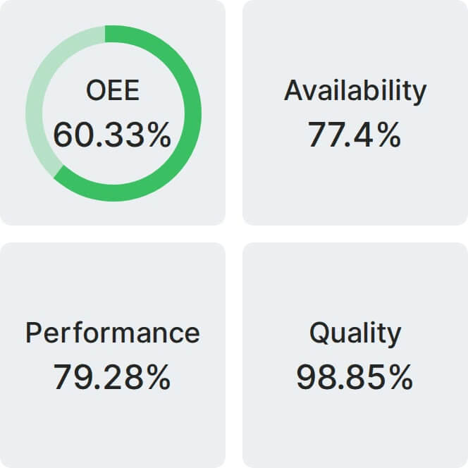
Real Fabrico tiles, sample data.