


 Login
 Blog

Danfoss VLT Fault Codes: What the Alarms Mean and How to Fix Them

When a Danfoss VLT drive trips, it shows an alarm number such as Alarm 7 or Alarm 13 and stops the motor. Tally trips by drive and shift, and a downtime analysis will show which alarm costs the most.
This guide covers the Danfoss VLT fault codes a maintenance team meets most often, what each one means, the usual cause, and how to clear it. The numbers below are the modern FC-series scheme used by VLT AutomationDrive FC 301 and FC 302, VLT HVAC Drive FC 102, VLT AQUA Drive FC 202 and VLT AutomationDrive FC 360. Older VLT 2800, 3000, 5000 and 6000 drives use a different numbering, so always confirm against the manual for your exact model.
Key takeaways
- Danfoss splits events into warnings and alarms. A warning lets the drive keep running while it flags a problem; an alarm trips the drive and latches until you reset it. Many conditions appear first as a warning, then as an alarm if they persist.
- The trips you will meet most are Alarm 7 DC overvoltage, Alarm 8 DC undervoltage, Alarm 9 inverter overloaded, Alarm 13 overcurrent and Alarm 14 earth fault.
- Most alarms point away from the drive: the supply, the load, the motor cable, or the cooling. An alarm that returns on restart means the cause is still there.
How a Danfoss VLT alarm works
The VLT watches its measured values continuously: DC link voltage, output current, heatsink temperature, and the motor thermal model. When a value leaves its safe window the drive raises a warning first where it can, and trips on an alarm when the condition crosses the trip limit.
The display shows the number, the drive coasts the motor to a stop, and the alarm latches. Read the number as a pointer, not a verdict. Alarm 7 DC overvoltage does not mean the drive is broken; it means the DC link climbed too high, usually because a high-inertia load decelerated faster than the drive could dissipate the returned energy.
Danfoss VLT FC-series fault code reference
The warnings and alarms most common on the shop floor, with the number, the name, and the usual cause. The full list for your model is in its programming guide.
| No. | Warning / Alarm | Usual cause |
|---|---|---|
| 2 | Live zero error | A 4-20 mA reference signal was lost |
| 4 | Mains phase loss | A missing or badly unbalanced incoming supply phase |
| 7 | DC overvoltage | DC link too high: fast decel of a high-inertia load, or a line surge |
| 8 | DC undervoltage | DC link too low: supply dip, interruption, or a weak feed |
| 9 | Inverter overloaded | The drive ran above its current rating for too long |
| 10 | Motor ETR over temperature | The motor thermal model reached its limit (overload) |
| 11 | Motor thermistor over temperature | A wired motor thermistor or PTC tripped |
| 12 | Torque limit | Output torque hit the configured limit |
| 13 | Overcurrent | The peak current limit was exceeded (jam, short ramp, fault) |
| 14 | Earth fault | Current leaking from an output phase to ground |
| 16 | Short circuit | A short across the motor output or in the drive |
| 17 | Control word timeout | Fieldbus control word stopped updating |
| 29 | Heatsink over temperature | The power module ran too hot: cooling or ambient |
| 30 / 31 / 32 | Motor phase U / V / W missing | An open output phase to the motor |
| 38 | Internal fault | An internal drive fault, with a subcode for the subsystem |
The drive tripped. What happened on the line just before? Fabrico puts stops on connected machines on the line timeline, so you can give the stop a reason and see what it cost, and where a camera covers the line, you see the minute before the alarm.
Fixing the alarms you will actually see
Safety first: a VFD stores dangerous energy in its DC link capacitors after the supply is switched off. Before you open the drive, touch its terminals or disconnect the motor cable, lock out the supply, wait at least the discharge time printed on the drive label and in the manual (4 to 15 minutes on FC 301 and FC 302 drives up to 75 kW), and confirm with a meter that the DC link has discharged.
Live voltage checks are for qualified electricians only, with a meter rated for the circuit and the PPE your site requires.
Alarm 7 DC overvoltage. The DC link went over its limit. On a real line this is almost always a deceleration problem: a loaded conveyor or a high-inertia fan is stopped faster than the drive can bleed off the energy the motor returns.
Extend the ramp-down time, enable the overvoltage control, or fit a brake resistor sized for the load. This is the same physics as a VFD overvoltage fault on any brand.
Alarm 8 DC undervoltage. The DC link dropped too low. Look upstream: a sagging supply, a loose incoming terminal, or a shared feed with a large motor or welder that pulls the line down on start. Confirm the input voltage under load.
Alarm 9 inverter overloaded and Alarm 10 motor over temperature. Alarm 9 is the drive protecting itself; Alarm 10 is the motor thermal model. Both usually mean the load grew or the duty is heavier than the sizing. Check the mechanical load, then confirm the motor data in the parameters matches the nameplate.
Alarm 13 overcurrent. Output current spiked past the peak limit. Check the mechanics first (a jam or seized bearing), then the acceleration ramp, then the motor cable. This is closely related to a VFD overcurrent fault.
Alarm 14 earth fault and Alarm 16 short circuit. Both are genuine electrical faults, not nuisance trips. With the drive locked out and discharged, disconnect the motor cable from the drive output terminals, then megger the motor and the motor cable, inspect the glands and terminations for damage or moisture, and repair before running again.
A recurring earth fault on the same motor points to failing winding insulation and planned replacement, not repeated resets. See ground fault protection.
Alarm 29 heatsink over temperature. The power module overheated. With the drive locked out and discharged, clean the heatsink, check the cooling fan and enclosure ventilation, and confirm the ambient temperature. A drive in a sealed panel next to a heat source will trip on a hot day even when nothing electrical is wrong.
Reading W12, A7, A9, A60 and alarm 84 on the display
The LCP shows a warning with its warning number and flashes an alarm with its alarm number in brackets after the text, for example Earth Fault [A14]. Read the letter and the number separately: W12 is warning 12, A9 (alarm 09) is alarm 9, and A7 and A10 are alarm 7, DC overvoltage, and alarm 10, motor ETR over temperature, both in the table above. The number names the same event in both cases; the letter tells you whether the drive has only warned or has tripped.
- W12, torque limit: the torque has exceeded parameter 4-16 Torque Limit Motor Mode or 4-17 Torque Limit Generator Mode. Parameter 14-25 Trip Delay at Torque Limit decides whether it stays a warning or is followed by an alarm. If it appears during ramp-up, extend the ramp-up time; during ramp-down, extend the ramp-down time; while running, check the application for excessive current draw before you raise the limit.
- Alarm 9, inverter overload: the drive has run with more than 100% overload for too long. The electronic thermal inverter counter warns at 98% and trips at 100%, and the drive cannot be reset until the counter is below 90%. Compare the output current on the LCP with the drive rated current and with the measured motor current.
- A60, external interlock: a digital input signals a fault outside the drive and the external interlock has commanded the trip. Clear the external fault, apply 24 V DC to the terminal programmed for external interlock, then reset the drive.
- Alarm 84, no safety option: the safety option was removed without a general reset. Reconnect the safety option.
Source: VLT AutomationDrive FC 301/FC 302 Operating Guide (AQ267037727118en-000101), chapter 7.
How to clear a Danfoss VLT alarm
Do not reset an alarm until you know why it tripped. Once the cause is fixed, most VLT alarms reset from the keypad Reset button, from a configured digital-input reset, over the fieldbus, or by cycling power.
A few trip-lock alarms, such as Alarm 16 short circuit or Alarm 38 internal fault, need a full power cycle and the DC bus fully discharged before they will clear. If the alarm returns the instant you run, the condition is still present, and clearing an earth fault or a short circuit just to keep the line moving risks a burned motor or a damaged drive.
Turn recurring alarms into a maintenance signal
One overvoltage trip is an event. The same VLT tripping on Alarm 7 every time it stops, or on Alarm 29 every summer afternoon, is a pattern that predicts a failure. Teams that stay ahead of drive faults do not just reset them, they log them: which alarm, which asset, which shift, how often. That record is where a stopped machine becomes a scheduled fix instead of a surprise.
This is what a CMMS and predictive maintenance software are for: capturing every trip against the asset, surfacing the drives that fault most, and turning a repeat trip into a scheduled work order before the next one stops the line. If drive faults are turning into unplanned downtime, read how Fabrico tracks downtime and how the recurring ones get caught early.
Related reading: VFD overvoltage fault, VFD overcurrent fault troubleshooting, and fault-code guides for other drives: ABB, Siemens Sinamics, Schneider Altivar and Yaskawa.
Alarm 10 motor ETR over temperature: the parameters behind it
Alarm 10 comes from the drive's electronic thermal relay (ETR), a software model of motor heating, not from a sensor in the motor. The FC 302 manual calls it Motor overload temperature and the FC 360 manual calls it Motor ETR overtemperature. You can watch the model live in parameter 16-18 Motor Thermal, shown in percent.
Parameter 1-90 Motor Thermal Protection decides what happens: with a warning option the drive warns once the counter passes 90 percent, and with a trip option it trips when the counter reaches 100 percent. The fault occurs when the motor runs with more than 100 percent overload for too long. Before you reset, work through these checks:
- Check whether the motor or the driven machine is mechanically overloaded.
- Check that parameter 1-24 Motor Current matches the nameplate full load current, and that the motor data in parameters 1-20 to 1-25 is correct.
- If the motor has a separately powered cooling fan, select it in parameter 1-91 Motor External Fan.
- Run an automatic motor adaptation (AMA) in parameter 1-29. It tunes the drive to the motor more accurately and reduces thermal loading.
How to recognize a trip lock
A trip lock shows as the warning light on and the alarm light flashing. A keypad reset, a reset input or a fieldbus reset will not clear it: remove input power, correct the cause, then restore power and reset.
On FC 301 and FC 302 the alarm table lists Alarm 13 overcurrent and Alarm 16 short circuit as trip lock alarms, so treat a repeating overcurrent as seriously as a short.
Alarm 2 live zero error
Alarm 2 only appears if parameter 6-01 Live Zero Timeout Function has been programmed. It trips when the signal on an analog input falls below 50 percent of the minimum value programmed for that input, for example below 2 mA on a 4 to 20 mA input whose minimum is set to 4 mA. The usual cause is a broken wire or a failed transmitter, so measure the signal at the analog input terminal before you replace anything.
Frequently asked questions
What is the difference between a warning and an alarm on a Danfoss VLT? A warning flags a problem while the drive keeps running; an alarm trips the drive and latches until reset. Many conditions show as a warning first and become an alarm if they persist or worsen.
What is the most common Danfoss VLT alarm? On most lines it is Alarm 7 DC overvoltage or Alarm 8 DC undervoltage, both supply and deceleration issues, followed by Alarm 9 inverter overloaded and Alarm 13 overcurrent.
How do I reset a Danfoss VLT alarm? Fix the cause first, then press Reset on the keypad, use a configured reset input, reset over the fieldbus, or cycle power. Trip-lock alarms such as Alarm 16 need a full power cycle.
Do these numbers apply to my older VLT drive? These are the FC-series numbers (FC 301, FC 302, FC 102, FC 202, FC 360). VLT 2800, 3000, 5000 and 6000 use a different scheme, so check the manual for your model.
Fabrico is a cloud-based MES and OEE platform for manufacturers, with computer-vision-verified OEE monitoring and maintenance management (CMMS) built in.
One Alarm 7 is a nuisance. The same alarm twice a shift is equipment downtime with a cost attached, and it only shows up as a pattern if stops are recorded with their duration and the reason operators tag, which is what automatic downtime tracking is for.
Stop chasing this fault by hand. Fabrico logs stops on connected machines against each machine's history, so a repeating fault shows up before it becomes a hard line stop, and the team can open a prioritized work order with the stop itself captured on video wherever a camera covers the line.
Fabrico is software for OEE, downtime tracking and maintenance. We do not sell parts or repair services.
Related articles








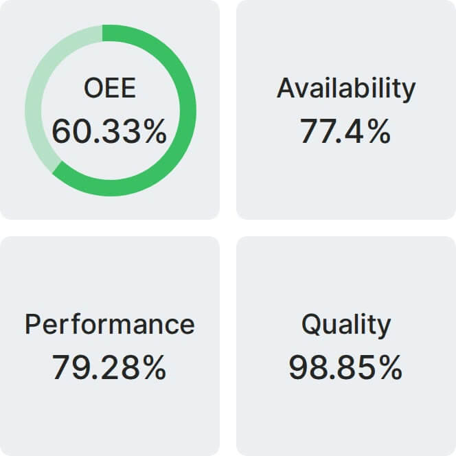
Real Fabrico tiles, sample data.