


 Login
 Blog

Computer Vision for Gearbox Manufacturing: Count Each Variant at Its Own Build Time

In short: computer vision for gearbox manufacturing counts reducers at the shimming bench and pallets at packing, so each variant earns its own build minutes.
- Flanks, backlash and run-in noise stay with the measuring room, the dial gauge and the test stand; the camera only counts.
- Ratio, frame size, mounting position, motor flange and gearmotor or reducer each land on different stations.
- Set an ideal time per frame size; one average time per bench turns the order mix into fake speed.
- Count each reducer once, at the bench exit, and take good units from the run-in pass.
Inspection measures a gear; counting says how many reducers left a station and when, and only counting feeds OEE.
A size 3 reducer at 20:1 and a size 5 gearmotor at 80:1 can leave the same shimming bench an hour apart. In this page's example one takes 24 bench minutes and the other 40, and a report that counts units calls them both one.
This guide covers industrial helical, helical-bevel and worm gear units and gearmotors. Car and truck transmissions are on computer vision for automotive parts manufacturing; wind turbine main gearboxes are outside it.
Computer vision for gearbox manufacturing: the variant-by-station matrix
A gear unit catalogue multiplies out fast: frame sizes times ratios times mounting positions times motor flanges, then a bare reducer or a gearmotor. Each change lands on one or two stations and passes the others untouched. The matrix shows where, for this page's example plant.
| Change per order | Shimming bench | Run-in stand | Paint | Packing |
|---|---|---|---|---|
| Ratio | Other gear set, same steps | Speed and noise differ | No change | No change |
| Frame size | 24 or 40 build minutes | Fixture and run time | More area | Pallet or crate |
| Mounting position | Plugs and breather placed | Oil fill for that position | No change | Position on label |
| Motor flange | Input adapter only | No change | No change | No change |
| Gearmotor or reducer | Motor mounting added | Runs on its own motor | More area | Heavier unit |
| Paint colour | No change | No change | Colour change | No change |
Read down a column and the shimming bench carries more rows than any other station: that is why its exit is the first count point, and why its ideal time has to move with the variant. A plant fills in its own matrix from its routings.
Explainer presented by Iris, Fabrico's AI-generated presenter: how an add-on camera counts output where a machine has no signal. Book a demo.
Plays from YouTube. Google may set cookies when you press play. Privacy policy.
Size 3 and size 5 are not the same unit: the trap of one ideal time
OEE performance compares the time a station earned, units times an ideal time, with the time it ran. On a gearbox bench a single ideal time turns the order mix into a speed gain or loss that never happened.
Take the worked example's shimming bench. In 410 running minutes it closed nine size 3 units at 24 minutes and four size 5 units at 40: 376 earned minutes, 91.7%. Give the bench one ideal time, the average of 32 minutes, and the same shift earns 13 x 32 = 416 minutes in 410 of running: 101.5%, which cannot happen.
Flip the mix: four size 3 and seven size 5 units, again 376 earned minutes with an ideal per size. The flat 32 minutes credits 11 x 32 = 352, and performance reads 85.9%. Bench and crew unchanged; the report calls one day a record and the other a slump.
| Shift mix, 410 running minutes | Ideal per frame size | One flat 32 minutes |
|---|---|---|
| 9 x size 3, 4 x size 5 | 376 min, 91.7% | 416 min, 101.5% |
| 4 x size 3, 7 x size 5 | 376 min, 91.7% | 352 min, 85.9% |
The fix is an ideal time per frame size, and per stage count where a two-stage and a three-stage unit share a frame. How to set one is in ideal cycle time for OEE, and the arithmetic of mixed rated speeds in OEE per SKU. In the example plant, ratio alone needs no time of its own: a 20:1 and an 80:1 set of one frame and stage count go through the same steps. Slow assembly that remains is real; the cycle time deficit shows how to chase it.
Ratio changes the gear set, and the machines that cut it already count
A new ratio means a new pinion and wheel, so the change lands upstream, on machines with their own controls. Blanks are turned from forgings or bar stock. Teeth are cut on hobbing machines, internal and shoulder gears on shaping machines, spiral bevel sets on bevel cutting machines and worm wheels on hobbers, then chamfered and deburred. Each machine counts its parts and reports run, setup and alarm states, so a ratio change shows there as a setup with a time, not as a gap.
Gears for industrial reducers are case carburised and quenched in sealed quench or pusher furnaces, or induction hardened, and some are then shot peened. A furnace load mixes ratios and sizes against one recipe, so measure it by load and furnace hours, as in OEE for heat treatment, not by gear. The grinders after it count their own parts again.
Each new set is checked in the measuring room. ISO 1328-1:2013 sets a tolerance classification system for the tooth flanks of cylindrical involute gears, and its stated purpose is a shared reference between the gear maker and the gear buyer. A counting camera adds nothing there.
The weak point upstream is the reason for a stop, not the count. When researchers at Chalmers analysed OEE records from 884 machines in 23 companies, almost half of the logged losses could not be classified because the plants' loss categories were missing or poorly described, and 90% of the classified stop time came from supporting work by operators, not the automatic process. On a hobbing cell that cuts many ratios, that means hob changes, fixture swaps, first-piece checks and waiting for blanks: give each its own code.
Mounting position decides the oil fill, and the run-in stand absorbs it
A reducer is ordered for the way it will sit: feet down, flange down, output shaft vertical. Its gears must run in oil whichever way it sits, so the fill quantity and the places of the breather, drain and level plugs follow the mounting position. The bench fits plugs and breather where the order says; the oil goes in at the run-in stand, or as a test fill drained for dry shipment.
On the stand each unit runs in both directions while noise, temperature and leaks are checked. The test code for that noise exists: ISO 8579-1:2002 specifies the conditions for determining the airborne sound emission of gear units and gearmotors, using engineering (grade 2) or survey (grade 3) methods. The pass, the fail and the measured values belong to the stand and its records. For OEE, read tested, passed and failed from the stand's PLC.
The mix shows at the stand as a queue. In the example plant a vertical size 5 unit takes longer to fill and run than a foot-mounted size 3, so the stand can fall behind the bench on a heavy mix. Count units into the queue at the bench exit and out of it from the stand's PLC, and the shift record says which of the two held output back.
Motor flange and gearmotor or reducer: one more bench, or none
A gearmotor gets its motor through an adapter and coupling or with a pinion directly on the motor shaft. Here the motor is bought in and described by standard codes: IEC 60034-7:2020 specifies the IM Code, a classification of types of construction, mounting arrangements and the terminal box position of rotating electrical machines. The flange is fixed before the motor arrives, and the gearbox side only picks the matching input adapter, which is why that matrix row holds a single cell.
For counting, gearmotor or bare reducer matters more than the flange. A bare reducer leaves the shimming bench finished. Where motor mounting has its own bench, a camera add-on there counts gearmotors out and the shimming bench counts reducers; where the shimming bench mounts the motor too, its exit is the only count point. Mixed hand and machine work is measured as in OEE on manual and hybrid assembly lines.
Housings follow the mounting choice too: a foot housing and a flange housing of one frame size are different parts. Housings are cast (see computer vision for foundries) and machined on horizontal machining centres with pallet changers, which count their own cycles.
Paint and packing absorb the order line, not the gear set
Paint colour comes from the customer's order, not from the gear design, so the paint booth sees a different mix from the bench, and each colour change costs a booth clean; ordering colours well is covered in SKU changeover sequence optimization. The example booth needs no count while packing is counted.
At packing, frame size decides the pallet or crate, and the mounting position goes on the label. A camera add-on over the packing area counts closed pallets and crates; set against run-in passes, that shows the gap between units passed and units ready to ship at each shift end.
Six ways a gearbox plant miscounts its output
Variants make double counts easy. These six errors appear on gear unit floors when counts are added without a plan, and each has a plain fix.
| What goes wrong | Effect on OEE | Fix |
|---|---|---|
| A re-shimmed reducer is counted again at the bench exit | Output too high, quality too good | One count per unit at the bench exit; rework gets its own code |
| Gearmotors counted at motor mounting and at run-in | Output doubled | One output point per unit; run-in pass gives good units |
| Shaft subassemblies added to finished units | Bench looks faster than it is | Count shafts at their own station |
| Units closed late on a shift and counted at packing next day | First shift looks slow, second looks fast | Count at the bench exit with its time stamp |
| Furnace output counted in gears | Heat treatment OEE swings with the load mix | Measure loads and furnace hours |
| Setup gears scrapped in the measuring room not subtracted | Hobbing quality too good | Read the measuring room's reject count |
Write the one count point per unit on the routing, next to the operation that owns it; BOM vs routing explains which document carries what.
Where the variants meet: one gearbox plant's flow
Gear sets by ratio and housings by mounting position converge on one bench, and bought-in motors join the gearmotors after it. The flow splits by product and joins again at the run-in queue.

Text version of this infographic
- Gear cutting: blank turning: machine signal, cycles from the lathe
- Gear cutting: hobbing and shaping: machine signal, gears from the control
- Gear cutting: gear measuring room: inspection system, flank checks, not Fabrico
- Heat treatment: carburising furnace: machine signal, loads and furnace hours
- Heat treatment: gear and bore grinding: machine signal, parts from the control
- Housings and shafts: housing machining centres: machine signal, pallet cycles
- Housings and shafts: shaft subassembly bench: camera count, shafts out
- Assembly and test: shimming and backlash bench: camera count, reducers out to run-in
- Assembly and test: motor mounting: camera count, gearmotors out
- Assembly and test: run-in test stand: machine signal, tested, passed, failed
- Shipping: packing and crating: camera count, pallets closed
- Every area: stop reasons: entered by the fitter or operator
- Footer: the camera add-on counts shafts, reducers and pallets; video for the minute of a stop is streamed on request and not stored in Fabrico
- Flank, backlash and run-in noise results stay with inspection and test
Book a demo to see size 3 and size 5 reducers credited at their own build minutes on one shift timeline.
Worked example: one mixed early shift at the shimming bench
Example numbers, no real plant. One final assembly and shimming bench with two fitters builds helical-bevel gearmotors in two frame sizes. Planned time is the early shift, 06:00 to 14:30, less a 30-minute break: 480 minutes. The build time standard is 24 bench minutes for a size 3 unit and 40 for a size 5 unit, set per frame size as above. A camera add-on counts shafts off the subassembly bench and closed units off the shimming bench, run-in results come from the stand's PLC, and the fitters key in stop reasons on a tablet at the bench.
Availability. The bench stood for 70 minutes: 40 waiting for a size 5 pinion shaft, 20 changing the press fixtures and the end float gauge from size 3 to size 5, and 10 after the induction bearing heater tripped. It ran 410 of 480 minutes: 85.4%.
Performance. It closed nine size 3 units, worth 216 build minutes, and four size 5 units, worth 160. That is 376 earned minutes in 410 minutes of running: 91.7%, with 34 minutes of slow assembly.
Quality. One size 5 unit failed run-in on noise and goes back for a new pinion setting: its 40 build minutes leave the good figure. 336 of 376: 89.4%.
OEE. 85.4% x 91.7% x 89.4% = 70.0%. Cross-check: 336 first-pass good minutes divided by 480 planned minutes is also 70.0%. The 20-minute size change is a loss only a mixed bench has.
The 40-minute shaft wait did not start at the grinder. Its control showed the bevel pinion finished at 06:30, but at the subassembly bench the camera add-on count showed no shafts leaving between 06:35 and 07:15, while that bench waited for a taper roller bearing from stores. Without the subassembly count, the shimming bench would carry the wait as its own and the grinder would get the blame.
What the lost minutes cost
A build minute has a value once the margin per unit is known. No public margin per frame size exists for gear units, so take an example contribution margin of EUR 432 per size 3 gearmotor and EUR 720 per size 5; both work out at EUR 18 per build minute. Both margins are example inputs for this page only. A plant uses its own margin per frame size, and Fabrico prices lost minutes from that figure.
| Loss | Minutes | Example value |
|---|---|---|
| Run-in reject | 40 | EUR 720 |
| Shaft wait | 40 | EUR 720 |
| Slow assembly | 34 | EUR 612 |
| Size change | 20 | EUR 360 |
| Heater fault | 10 | EUR 180 |
| Total | 144 | EUR 2,592 |
The 144 lost minutes are 480 planned minus 336 good, and 144 x EUR 18 = EUR 2,592 of contribution in one shift. Two limits keep that honest. It holds while the shimming bench is the constraint; if the run-in stand or painting holds output back, a lost bench minute is worth less. And the noise reject costs more than its 40 minutes: opening the unit, draining oil and a second run on the stand happen on the next shift and are left out here.
Ranked by money, the run-in reject and the shaft wait make EUR 1,440 of the EUR 2,592. The first sends the team to the stand's noise record and the backlash readings, the second to the subassembly bench and its bearing supply. With a plant's real margins a size 5 minute and a size 3 minute can differ, and the ranking follows; valuing output at SKU level shows why.
In Germany, VDMA's power transmission network counts more than 220 manufacturers of drive elements, gearboxes, electrical drive technology and linear technology, generating over 80 percent of estimated German production. A bench that loses EUR 2,592 in a shift is a cost a plant can remove without new orders.
What a counting camera sees when the next reducer is a different size
Variants matter to the camera too. In a peer-reviewed study in the Journal of Imaging, Pierleoni and colleagues at Università Politecnica delle Marche counted pieces an operator placed on a table at an assembly line. In a test with pieces of another size and shape, their trained detector, "which was trained on the original product type, made several mistakes, due to its unsuitability for the different objects placed on the table during this test." Their simpler blob method, re-set with new parameters, matched its earlier results. They also report that their improved counter "counts when there are no hands in the framed area."
The limits: one table, one camera and small black-painted steel parts, not reducers. No Fabrico accuracy figure is given on this page. What carries over is what to plan for:
- Frame sizes: a size 3 and a size 5 unit look different from above, so test the count on both sizes before trusting it.
- Hands in view: fitters reach over a unit to fit covers, so aim at the outfeed track, where a closed reducer sits alone.
- Oil and light: a greasy bench and changing daylight alter the image, so ask for steady lighting over the count point.
Questions for any OEE or camera vendor:
| Question | A good answer |
|---|---|
| How does a bench earn minutes across frame sizes? | A build time per frame size, credited when the unit leaves the bench. |
| How is the count set up for another frame size? | Shown on a test at the bench with both sizes, before the pilot starts. |
| Who supplies run-in passes and fails? | The stand's PLC or test computer, with no retyping. |
A lens above a shimming bench also sees the fitters. Agree the purpose with the team before mounting, involve any works council early, and put in writing which roles may open bench footage and for what. Report by station and shift, never by person; Fabrico's camera add-on counts reducers, shafts and pallets, not people.
Where Fabrico fits on a mixed gearbox floor
Fabrico is cloud OEE software that also covers light MES work. On a gear unit floor it does three jobs today:
- Lathes, hobbing and shaping machines, grinders and machining centres: run state and part counts come from the CNC controls, so hob changes, setups and waits for blanks show on the timeline with their own codes. The furnace reports loads and hours.
- Subassembly, shimming, motor mounting and packing: the camera add-on counts shafts, closed reducers, gearmotors and pallets. If the shimming bench stood at 06:40, the assembly lead clicks that stop on the shift timeline to see the video for the minute of the stop, streamed on request by the camera add-on and not stored in Fabrico.
- Run-in stand: tested, passed and failed come from its PLC, against the build minutes set per frame size.
Stop reasons are entered at the bench or machine by the fitter or operator, on a tablet or phone. Each station and shift shows its lost minutes in euros, based on the plant's margin, and the losses can be read per product, the idea behind downtime by SKU. Browser, iOS and Android apps are available, and exports run by REST API, webhooks, Excel or CSV.
Roadmap: the camera add-on flagging a quiet bench or a growing row of reducers at the run-in stand, and suggesting a stop reason for the fitter to accept or correct.
Outside Fabrico: gear measurement, backlash and end float readings, run-in noise and vibration values, test certificates and serial records. Fabrico does no inspection; rejects from those systems arrive in OEE as counts.
Read more on the Fabrico OEE and MES solution. Counting by camera is covered in camera-based OEE software and manufacturing vision systems for OEE.
FAQ: gearbox variants and counting
Which gearbox station should get the first camera?
Over the exit of the final assembly and shimming bench, where finished reducers leave for the run-in stand. Hobbing machines, grinders and the stand report through their controls, so the bench is the step with no count of its own.
Should a gearbox bench have one ideal time or one per frame size?
One per frame size, and per stage count where stages differ. A single average time credits a shift of small units with more than 100% performance and a shift of large units with too little.
How is a reducer counted when it fails run-in and is re-shimmed?
Once. It leaves the first-pass good figure when the stand rejects it, and the time spent opening it and resetting the shims is booked at the shimming bench under a rework code, so it does not inflate output.
Where is a gearmotor counted: at motor mounting or at the run-in stand?
At one point only. Count output where the motor has been mounted and the unit leaves the bench, and take good units from the run-in pass. Counting at both places doubles output.
Does a new ratio or mounting position need its own count point?
No. A ratio change lands on gear cutting machines that count their own parts, and a mounting position on the bench fittings and the oil fill. The unit still counts once, at the bench exit.
Want to see a mixed shift at the shimming bench priced by frame size? Book a demo.






Latest from our blog






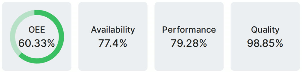
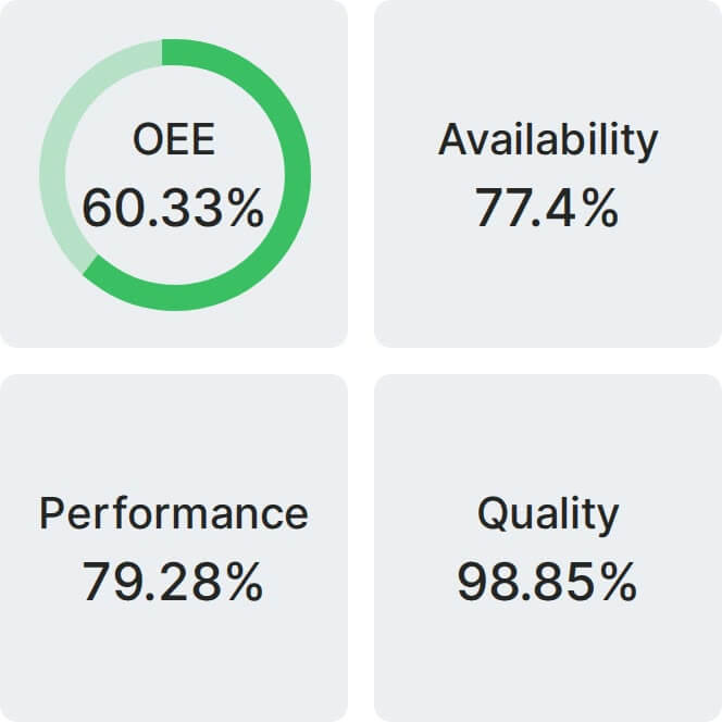
Real Fabrico tiles, sample data.