


 Login
 Blog

Computer Vision for Electric Motor Manufacturing: Find the Station That Holds Output Back

In short: Computer vision in electric motor manufacturing counts stators and motors at hand benches without a machine count, showing which station holds output back.
- Inspection is a separate job: test benches and inspection systems judge the motor; the camera add-on only counts what leaves a station.
- Run the queue test first: count stators into and out of each buffer for one shift.
- Read a batch oven when the load closes: stators left behind mean the oven holds output; empty slots mean it waits.
- Price only the constraint's lost minutes as lost motors, and only while orders wait.
The queue test: count stators into and out of each buffer
A motor plant has more queues than stations. Stacks wait for the winders, wound stators for the benches, laced stators for the oven, rotors for assembly. The constraint is the station whose queue in front grows through the shift while the queues after it run dry.
The test needs no software. For one shift, count what sits in each buffer at the start, at each oven load and at the end, plus what goes in and out. Two readings settle most arguments:
- A queue that grows from start to end sits in front of a station that cannot keep up.
- A queue that empties while the next station waits means that station is starved, so the constraint is further upstream.
Batch steps need one extra rule, and a motor plant has two of them: the lamination press and the varnish oven. Read their queues at the moment a batch closes, not when the pile looks biggest. Here is one late shift in the example plant used throughout this page:
| Buffer | Start, in, out, end | Reading |
|---|---|---|
| Stacks before winding | 40, 140, 128, 52 | The press runs ahead in pallets; no signal on its own |
| Wound stators before the lacing benches | 18, 134, 126, 26 | Grew all shift: the benches cannot keep up |
| Laced stators before the oven | 6, 122, 124, 4 | Nothing left behind when each of 4 loads closed |
| Varnished stators before assembly | 24, 94, 118, 0 | Empty for 52 minutes while assembly waited |
| Rotors before assembly | 20, 130, 118, 32 | Rotors piling up: the feeder is ahead |
The pile in front of the oven looked like the problem every afternoon. The counts say otherwise: the oven closed four loads at an average of 31 stators against racks that hold 48, and left nothing behind (the four still waiting at 22:00 arrived after the last load). The lacing benches are the constraint, and a bigger oven would have added no motors that shift. The method is the same one behind any bottleneck analysis in manufacturing; a motor plant just has more batch steps to trip over.
Explainer presented by Iris, Fabrico's AI-generated presenter: how an add-on camera counts output where a machine has no signal. Book a demo.
Plays from YouTube. Google may set cookies when you press play. Privacy policy.
How stators, rotors and the oven feed one assembly line
The example plant builds low voltage induction motors in IEC frame sizes 100 and 132 (shaft height in millimetres). One press feeds two flows. Stators go through winding and insertion, hand benches, a surge test and the varnish oven. Rotors go through aluminium die casting, shaft pressing, turning and balancing. Both meet at assembly, then the end-of-line test, the rating plate and packing.
Two features of this layout drive everything that follows. The rotor line is a feeder, so it should always run slightly ahead. The oven is a batch, so its queue rises and falls in waves. Switchgear and transformers have their own page: computer vision for electrical equipment manufacturing.
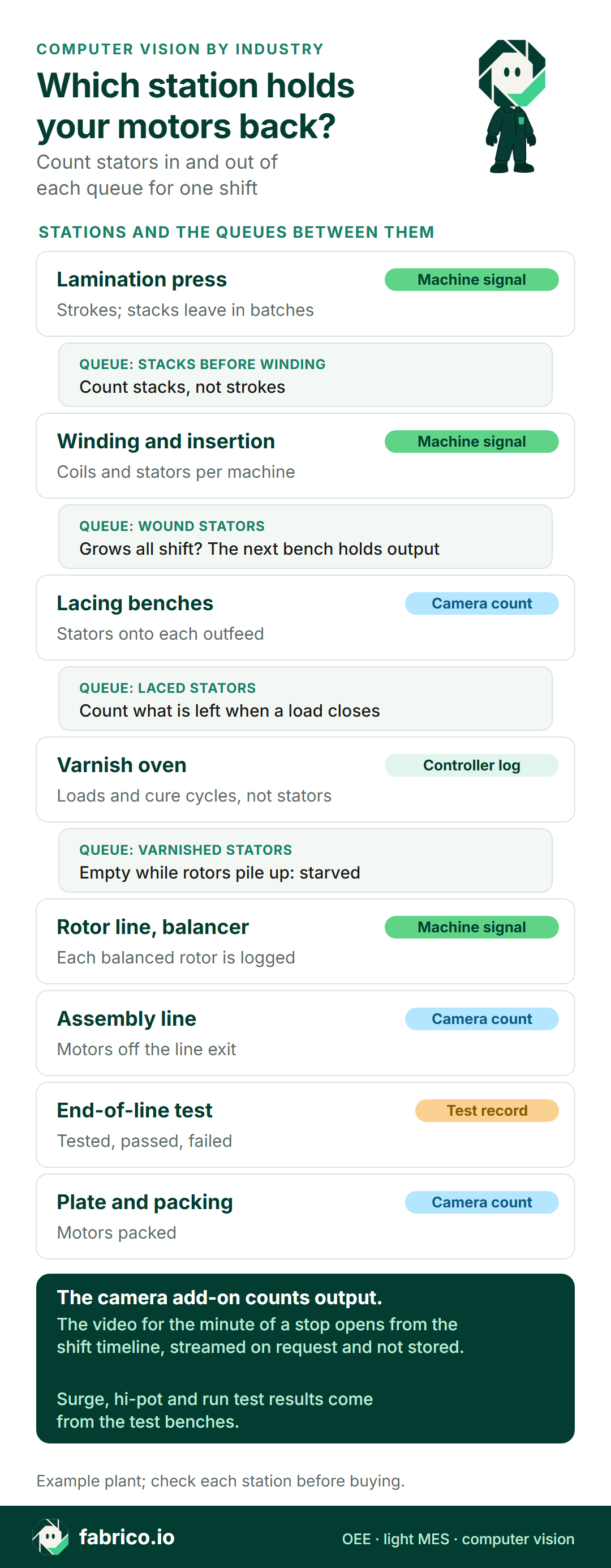
Text version of this infographic
- Lamination press: machine signal. Strokes; stacks leave in batches.
- Queue, stacks before winding: count stacks, not strokes.
- Winding and insertion: machine signal. Coils and stators per machine.
- Queue, wound stators: grows all shift? The next bench holds output.
- Lacing benches: camera count. Stators onto each outfeed.
- Queue, laced stators: count what is left when a load closes.
- Varnish oven: controller log. Loads and cure cycles, not stators.
- Queue, varnished stators: empty while rotors pile up means starved.
- Rotor line and balancer: machine signal. Each balanced rotor is logged.
- Assembly line: camera count. Motors off the line exit.
- End-of-line test: test record. Tested, passed, failed.
- Plate and packing: camera count. Motors packed.
- The camera add-on counts output. The video for the minute of a stop opens from the shift timeline, streamed on request and not stored. Surge, hi-pot and run test results come from the test benches.
- Example plant; check each station before buying.
Lamination press: it already counts, but strokes are not stacks
The press knows its strokes per minute, its die changes and its stops, and that signal is good. The trap is the unit. A 2021 University of Sheffield thesis on winding and stator manufacturing describes the step plainly: "The mandrel releases the laminate stack once enough laminates have been collected. At this point, the process ceases to be continuous and becomes more similar to a batch process."
So the press counts strokes, and winding needs stacks. In that thesis's cost model one stack holds 286 laminates. The count that matters for the queue test is stacks released, by part number, because a change to a new stack height changes how many strokes make one stack. Many progressive dies also cut the rotor lamination from the centre of the stator blank, so one press feeds both flows, and a press stop starves the rotor line and the winders at the same time.
No camera is needed here: read the press, and count stacks onto the pallet from the stacking signal or a sensor (see OEE for stamping and press operations).
Winding, insertion and the hand benches after them
Coil winding and insertion machines count coils and stators and report their own stops; read them. The same thesis notes that hand winding is "only relevant to small order sizes or prototypes", which is why most plants wind and insert by machine and keep people for the steps after.
Those steps are where the count disappears. At connection and lacing benches, operators join the coil groups, fit sleeving and terminal leads, and lace the end turns with cord. A bench has no PLC, and often the only record is an end-of-shift tally. That is the place for a camera add-on: it counts stators onto each bench's outfeed, so each bench gets its own output per hour and its own gaps.
Set the ideal time per frame size, not per bench. In the example, a frame 100 stator takes 10 minutes at one bench and a frame 132 stator 16, so the four-bench cell earns 2.5 or 4 minutes per stator. One average rate would flatter the shift that runs small frames (see theoretical vs actual cycle time). An IE4 version of a frame with a longer stack or more copper gets its own ideal time too.
The surge and hi-pot test after lacing logs pass and fail per stator. That record, not the camera, gives the quality count for the benches.
Hairpin stators: hundreds of pin variants before one stator counts
Traction motor plants build stators from flat copper hairpins instead of round wire. A 2024 Procedia CIRP paper from the Karlsruhe Institute of Technology lists the chain after bending: "the gripping and pre-assembling of all the individual hairpins in an assembly device to form the desired winding scheme, the insertion of all hairpins into the stator lamination stack, the twisting of the open coil ends and finally the contacting of the coil ends by laser welding."
The paper says a stator can need "several hundred individual hairpins which in turn can have a variety of different geometries", and for its cost estimate it assumes "a cycle time of 4 seconds for gripping and pre-assembling a single hairpin". Take an example stator of 240 hairpins: at 4 seconds each, pre-assembly alone is 16 minutes for one gripper. Forming machines count hairpins by the thousand, and none of those counts is a stator.
So run the queue test on nests and stators, not pins: nests waiting for insertion, stators waiting for twisting and welding. Automated lines have PLC counts. The camera add-on earns its place where people still load nests or fit connection rings by hand, common in small series and prototype cells. For e-drive supply, see OEE for automotive tier 1 suppliers.
The varnish oven: its machine signal counts loads, so read the queue when one closes
Impregnation is where most plants misjudge the constraint. Trickle lines cure stators in a steady flow and count their own output. Dip and bake and vacuum pressure impregnation (VPI) work in batches. The Electrical Apparatus Service Association (EASA) describes VPI as "placing the part in a vessel, drawing a dry vacuum, introducing resin, applying pressure, and then curing the part in an oven." It adds: "The curing time depends on the part temperature and the varnish or resin's rated curing temperature."
Two consequences follow. The oven controller logs loads and cure cycles, not stators, so someone counts stators into each load. And a heavy frame 132 stator takes longer to heat through than a frame 100, so a mixed load runs at the pace of its heaviest part: the oven's ideal time belongs to the load recipe, not to a stator (see OEE for batch processes).
Then the queue rule. A pile in front of the oven at 17:00 says nothing: the oven loads every two hours and the pile is meant to build. Count when the door closes: stators in, slots empty, stators left on the floor. Empty slots and nothing left behind, load after load, means the oven waits for the benches. Stators left behind at each closing means the oven is the constraint.
Rotor line, assembly and the rating plate: count once, at the plate
The rotor line is the feeder. Die casting counts shots (OEE for high pressure die casting), the turning centre counts parts, and the balancer logs each rotor against the grade the design calls for (ISO 21940 balance quality grades). Rotors piling up while stators run out means the feeder is ahead. If the reverse happens, check the balancer first: a rotor that needs correction takes its time twice.
Assembly lines for small motors are often manual or semi-automatic: stator pressed or shrunk into the housing, rotor inserted, bearings, end shields, fan and terminal box fitted. A line without a PLC count is the second place for a camera add-on, at the line exit. When this line waits, an empty stator buffer with rotors piling up is starvation, not an assembly loss.
The end-of-line test bench logs each motor it tests, with pass or fail, and that record is the quality count for the line. Then comes the rating plate. In the EU, Regulation (EU) 2019/1781 on motors and drives sets IE3 as the floor for most three-phase motors from 0.75 to 1,000 kW from 1 July 2021, and from 1 July 2023 three-phase motors from 75 to 200 kW with 2, 4 or 6 poles "shall correspond to at least the IE4 efficiency level", with exceptions such as brake motors. It also requires the rated efficiency and the IE class, "as well as the year of manufacture shall be durably marked on or near the rating plate of the motor."
CEMEP, the European association of electrical machine makers, adds a detail that matters on the floor: for a motor rated for several voltages, frequencies or powers, the plate carries at least "the lowest efficiency value and the associated IE code". So plates are per variant and printed after the test, and a plate printer or laser marker that logs each plate is a cleaner count of finished motors than the packing table. Where there is no such log, the camera add-on counts motors packed.
Start here: what to count first, in order
| Order | Count point | Source | What it answers |
|---|---|---|---|
| 1 | Wound stators into and out of the lacing benches | Winding machine count in, camera add-on out | Is the bench queue growing? |
| 2 | Stators per oven load, empty slots, stators left behind | Tablet entry at door close, oven controller | Is the oven waiting or holding? |
| 3 | Varnished stators and rotors at assembly | Camera add-on at the line exit, balancer log | Is assembly starved, and by which flow? |
| 4 | Motors tested and plated | Test bench record, plate log | Finished, first-pass good motors |
| 5 | Stacks released at the press | Press signal, stack sensor | Is the press feeding both flows? |
The first two settle the constraint in one shift; three and four turn it into OEE and money. Stop reasons come from people: the bench or line lead adds the reason on a tablet or phone, from a short list (kit missing, frame change, waiting for stators, test fail).
Once the benches are known as the constraint, pacing stator release to them keeps the queue in front from running dry or flooding (drum-buffer-rope). To prove a fix worked, compare the bench queue and output before and after (real-time OEE for bottleneck analysis).
Want to see bench, oven and assembly counts on one shift timeline? Book a demo.
One late shift at the lacing benches, priced
The example shift, with example inputs a plant replaces with its own. The four-bench lacing cell runs from 14:00 to 22:00. The 15-minute paid break is off the plan, so planned time is 465 minutes.
- Stops, 47 minutes: lead and sleeving kits ran out at 15:10 and the cell waited 30 minutes; one frame change from 100 to 132, with new lead sets and lacing cord, took 17.
- Run time, 418 minutes. The camera add-on counted 96 frame 100 stators and 30 frame 132 stators off the outfeeds: 96 x 2.5 + 30 x 4 = 360 earned minutes.
- Slow running, 58 minutes: 418 minus 360. Two operators were in their first month on frame 132.
- Test fails, 13 minutes: the surge test failed 2 frame 100 and 2 frame 132 stators, 2 x 2.5 + 2 x 4 = 13 minutes of the cell's time.
Availability is 418 / 465 = 89.9%. Performance is 360 / 418 = 86.1%. Quality is 347 / 360 = 96.4%. OEE is 0.899 x 0.861 x 0.964 = 74.6%, the same as 347 good minutes out of 465.
Now the money. Only the constraint's lost minutes are lost motors, and only while orders are waiting. No public margin exists for a frame 100 motor, so the inputs are examples: a selling price of EUR 240 and a contribution margin of 25%, which sits between the 9.53% pre-tax operating margin and the 31.82% gross margin that NYU Stern lists for US electrical equipment makers (January 2026 data). That is EUR 60 a motor, or EUR 24 per ideal bench minute at 2.5 minutes a stator.
| Loss at the benches | Minutes | Priced as | Money |
|---|---|---|---|
| Kit wait | 30 | Lost motors at EUR 24 a minute | EUR 720 |
| Frame change | 17 | Lost motors at EUR 24 a minute | EUR 408 |
| Slow running | 58 | Lost motors at EUR 24 a minute | EUR 1,392 |
| Stops and slow running | 105 | 42 motors not built | EUR 2,520 |
| Test fails, repaired | 13 | Repair crew time only | EUR 67 |
That is EUR 2,520 a shift, or EUR 105,840 over a month of 42 shifts like it, while orders wait. The kit wait alone is EUR 720 a shift and needs no capital, only an earlier kitting call. Repair is crew time: 4 stators at an example 25 minutes each is 100 minutes, about EUR 67 at the EUR 40.3 an hour that Eurostat reports for euro area industry in 2025. Those stators ship a shift later, so no margin is lost on them.
Price the wrong station and the answer flips. The oven ran 17 empty slots per load on average. Priced as lost output, the 68 empty slots of the shift would look like EUR 4,080 of margin. None of it was lost: the benches had nothing more to give the oven, so oven capacity buys no motors until the benches move.
What a camera can count at a motor bench, and what stays with inspection
The camera add-on counts objects that leave a station: a laced stator on the outfeed, a motor leaving the line, a box on the pallet. It counts poorly where hands cover the work. A 2023 Sensors study from Hamburg University of Technology on recognising manual assembly steps notes that "tools that are handled manually may be heavily occluded and visual identification can be considered challenging", and that judging progress from the product fails "if the assembly situation is chaotic and affected by occlusions". Its real-time set-up ran at "just above 4FPS". These are lab limits, not a counting benchmark.
In a motor plant: count at the outfeed, not over the lacing hands; give each bench one outfeed position so a stator cannot be set down twice in view; light the outfeed evenly, because enamelled copper throws glare. Check the count against the surge test log for a few shifts before trusting it (how accurate a camera part count is).
The camera does not judge the winding. Insulation, surge, hi-pot, resistance and balance results come from the test benches and the balancer; weld or air gap checks belong to inspection systems. Questions for any vendor:
| Question | Good answer |
|---|---|
| Can each frame size keep its own ideal time? | Yes, set per product by the plant. |
| How are stators counted into an oven load? | A load count kept apart from cure time. |
| Can a bench count sit next to the surge test log? | Yes, and the test log owns quality. |
| What if a hand covers the outfeed? | A stated limit, tested against a reference count. |
| Can hairpin lines count nests and stators, not pins? | Yes, the unit is set per station. |
| Where does the video go? | The minute of a stop, streamed on request and not stored. |
In plants with a works council, agree the camera before it is mounted: what it counts, what it never does (no tracking of people), and who may open video. See GDPR and production line cameras.
Where Fabrico fits in a motor plant
Fabrico is OEE and light MES software. It takes run, stop and count from the press, winders, die casting and balancer through the PLC, a sensor or a counter; leads add stop reasons on a tablet or phone. OEE and losses show by station, line and shift, priced from the plant's own SKU price or margin.
The camera add-on counts output where no machine does: bench outfeeds, a manual line exit, the packing table. Where a camera covers the line, the video for the minute of a stop can be opened from the shift timeline; it is streamed on request and not stored. Camera-detected stops and stop-reason suggestions are on the Roadmap; today a person adds the reason.
Fabrico does no inspection and runs no motor tests; the test benches and inspection systems keep those jobs, and their pass and fail counts can feed quality. Fabrico supplies the rates and counts; the plan lives in the ERP, APS or spreadsheet. Counts and losses can be pulled out by REST API or webhooks, or exported to Excel or CSV. See the computer vision OEE software feature, the MES and OEE software overview and light MES for the full scope, and manufacturing vision systems for OEE for how camera counts sit next to machine signals.
Questions motor plant managers ask
Where does a camera add-on go first in an electric motor plant?
At the outfeed of the hand benches after winding, usually connection and lacing, because no machine counts there and the queue test needs their output. The assembly line exit and the packing table come next.
Is the varnish oven usually the bottleneck in motor manufacturing?
Sometimes, but a pile in front of a batch oven proves nothing. Count the stators left on the floor when each load closes. If none are left and slots run empty, the oven is waiting for the stations before it.
Can a camera count hairpins?
It is the wrong unit. Forming machines already count hairpins, and the queue test needs stators and filled nests. A camera add-on fits where people load nests or fit connection rings by hand.
Does the camera replace the surge test or the end-of-line test?
No. The camera add-on counts output. Surge, hi-pot, resistance and run tests stay with the test benches, and their pass and fail records give the quality count.
How do IE3 and IE4 versions of one frame change OEE?
Where the IE4 build of a frame has a longer stack or more copper, it takes longer at winding and at the benches. Give it its own ideal time, or a shift of IE4 motors looks slow when it is not.
Want to see lacing benches, the varnish oven and assembly counted on one timeline? Book a demo.
Related articles






Latest from our blog




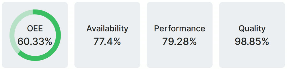
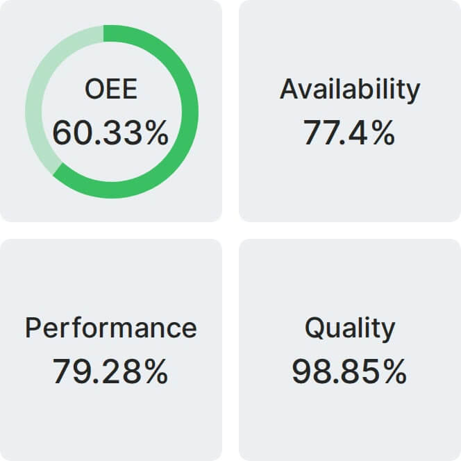
Real Fabrico tiles, sample data.