


 Login
 Blog

Computer Vision for Wind Turbine Blade Manufacturing: A Pilot That Finds Why Moulds Wait

In short: in blade plants, computer vision for OEE counts manual feeder work, like root inserts seated in carriers, and shows when a shell mould waits.
Finding wrinkles, voids or a weak bond line is inspection, done by NDT and ultrasonic systems; counting output is a separate job.
- The shell mould is the constraint: blade plants plan main mould gating around 24 hours, so a late feeder costs mould time.
- Pilot one camera add-on over the root insert carrier table, judged against the mould team's carrier sign-off.
- The proof is the mould sheet: did a shell mould wait for root inserts, and does the bench timeline show why?
- Price mould minutes from the plant's own blade margin, and only while blade orders wait.
- Widen to the finishing and grinding bays next, where blades queue between demould and paint.
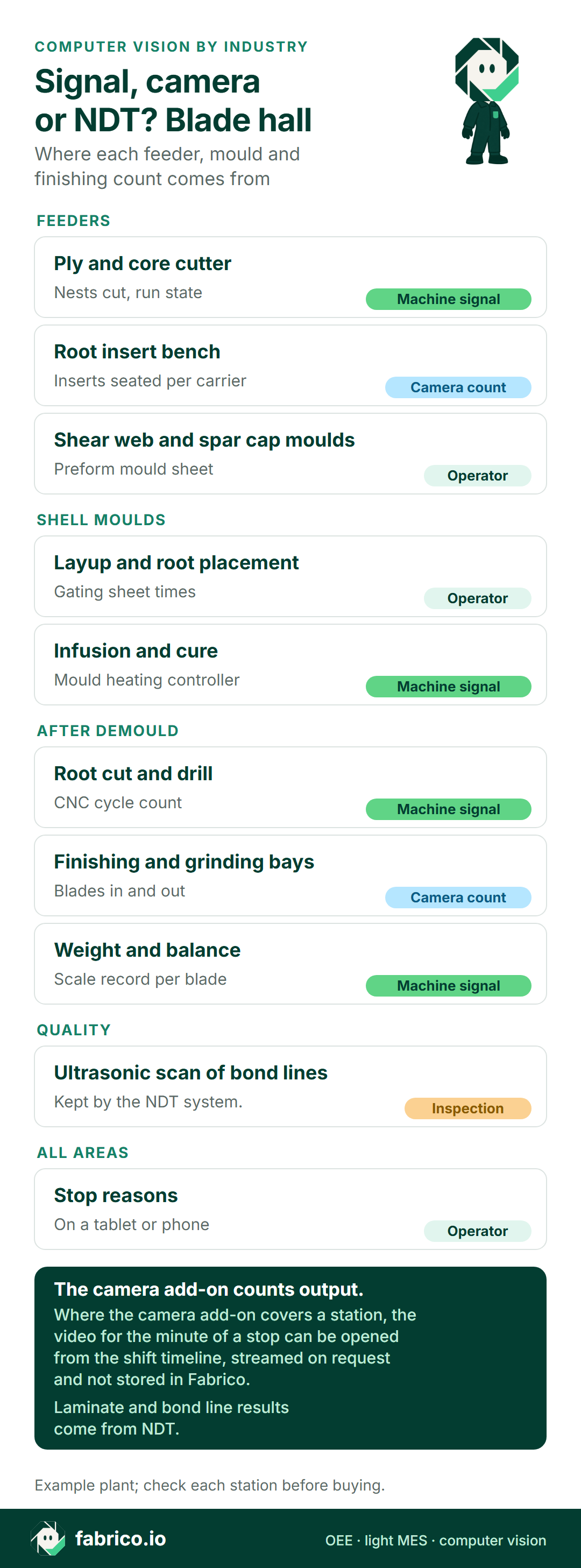
Text version of this infographic
- Title: Signal, camera or NDT? Blade hall. Where each feeder, mould and finishing count comes from.
- Feeders: ply and core cutter: machine signal, nests cut and run state.
- Feeders: root insert bench: camera count, inserts seated per carrier.
- Feeders: shear web and spar cap moulds: operator, preform mould sheet.
- Shell moulds: layup and root placement: operator, gating sheet times.
- Shell moulds: infusion and cure: machine signal, mould heating controller.
- After demould: root cut and drill: machine signal, CNC cycle count.
- After demould: finishing and grinding bays: camera count, blades in and out.
- After demould: weight and balance: machine signal, scale record per blade.
- Quality: ultrasonic scan of bond lines: inspection, kept by the NDT system.
- All areas: stop reasons: operator, on a tablet or phone.
- Footer: the camera add-on counts output. Where the camera add-on covers a station, the video for the minute of a stop can be opened from the shift timeline, streamed on request and not stored in Fabrico. Laminate and bond line results come from NDT. Example plant; check each station before buying.
Computer vision for wind turbine blade manufacturing: the mould sets the pace
A blade factory is built around its main moulds. NREL's detailed wind turbine blade cost model splits the work into 15 operations, including material cutting, infusion, assembly, demould, trim, overlay, postcure, root cut and drill, surface preparation, paint, weight and balance, inspection and shipping preparation. Only three of them happen on the main mould: assembling the preinfused parts, the main infusion of the two half moulds, and the demould. NREL calls that block the gating cycle and notes that "Blade factories usually try to have the gating cycle time equal to 24 hours". The number of main moulds, and the minutes each one stands idle, decide how many blades leave the hall.
Everything else is a feeder or a follower. In the NREL model, spar caps, shear webs and root preforms are infused in their own moulds and inserted into the low pressure (LP) and high pressure (HP) skin moulds; bonded root inserts are "more and more commonly used". Behind the mould come trim, root machining, sanding and grinding, paint and balance. A late feeder makes the mould wait; a slow follower fills the hall until a demoulded blade has nowhere to go. The theory of constraints says protect the mould first.
The work is manual. For its 63 m reference blade, NREL estimates 1,134 labour hours and needs "teams formed of 19 and 18 workers" to hold the gating cycle. That size matches new US turbines: the US DOE Land-Based Wind Market Report 2024 states that "The average rotor diameter of newly installed turbines was 133.8 meters". Longer blades mean more inserts per root and more surface to sand.
Before anything is mounted, list what each station already records. Only a few manual benches and bays have neither a signal nor a sheet.
| Blade hall station | Record that exists | Pilot use |
|---|---|---|
| Ply and core cutting | Cutter PLC: nests cut, run state | Machine signal, not the pilot |
| Root insert bench | Kitter's tally sheet | Pilot station: camera add-on count |
| Shear web and spar cap moulds | Preform mould sheet | Later, if the mould waits |
| Shell mould layup | Gating sheet times | Referee: when the mould waited |
| Infusion and cure | Vacuum log, mould heating controller | Machine signal |
| Bonding and mould closing | Gating sheet | Referee |
| Root cut and drill | CNC program and cycle count | Machine signal |
| Finishing and grinding bays | Bay whiteboard | Next camera, Step 7 |
| Paint, weight and balance | Booth log, scale record | Operator or machine record |
| Ultrasonic scan of bond lines | NDT report | Inspection: not Fabrico, not this pilot |
Inspection stays where it is. NREL notes that an ultrasonic inspection step "is often performed on the bonding lines", and the NDT team owns every judgement about laminate and bond. A count says how many inserts were seated, never whether a bond line is good; bond line inspection stays with the NDT system. The blade standard IEC 61400-5 covers "manufacture (including associated quality management)"; the pilot adds counts beside that quality file and changes nothing in it.
Explainer presented by Iris, Fabrico's AI-generated presenter: how an add-on camera counts output where a machine has no signal. Book a demo.
Plays from YouTube. Google may set cookies when you press play. Privacy policy.
Seven steps for a first pilot at the root insert bench
Why this bench first? It feeds every shell mould. Kitters clean bushings, fit thread plugs and seat inserts into a carrier in root order, so every carrier gives dozens of counts to compare. And when it is late, a mould crew of 18 or 19 people waits. The guide to picking an OEE pilot line asks the same question: where does a count change a decision?
The plant sets its own pace; the records in the third column, not a calendar, move the pilot from one step to the next.
| Step | At the insert bench | Evidence kept | Moves on when |
|---|---|---|---|
| 1 | Kitters tally inserts per carrier; the mould team signs each carrier | Tally sheet, carrier sign-off, gating sheet | Every carrier has all three |
| 2 | One camera add-on over the carrier table, top view | Test frames the kitters and works council approved | Every slot is in view, no faces |
| 3 | Count rules for inserts, carriers and re-seats | Rule card at the bench | Kitters and shift lead sign it |
| 4 | Camera add-on count beside tally and sign-off | Proof sheet per carrier | The plant's own acceptance rule holds |
| 5 | Kitters add stop reasons on a tablet | Shift timeline | Unexplained gaps under the plant's limit |
| 6 | Carrier-full time against the mould's need time | Mould wait minutes, priced | Each wait has a bench cause |
| 7 | Widen, change or stop | Decision note | The plant manager signs it |
Two records referee the pilot, and neither belongs to the vendor: the mould team's carrier sign-off, which counts filled slots on arrival, and the gating sheet, which says when the inserts were needed and when they went in. The manufacturing software pilot design guide makes the same point: agree the referee before the first count.
Steps 1 and 2: a hand baseline, then one camera add-on over the carrier table
Step 1: hand baseline. The kitters tally inserts per carrier, not per hour, and write the blade serial and the half (LP or HP) on each carrier tag. The mould team counts the filled slots on arrival and signs the tag, and the mould lead writes on the gating sheet when the carrier was needed and when it arrived. The example uses 52 inserts per carrier; the real number comes from the plant's blade design. Hand tallies drift, as the page on manual data entry versus automated capture shows, which is why the sign-off, not the tally, is the referee.
Step 2: mount one camera add-on. A top view over the carrier table shows every slot, and hands only cross it while seating an insert. Hands hide parts: in the peer-reviewed HA-ViD human assembly video study (NeurIPS 2023), the authors note that "the left hand is less occluded because the side-view camera is mounted on the left-side of the participant", and that combining three views "offers a viable solution for mitigating occlusion challenges in industrial settings". So keep the kitter's body out of the line between lens and slot, fix the carrier in one spot, and allow a second view for a large carrier. Steel bushings throw glare, so diffuse the light, and keep the bench away from grinding dust.
No accuracy figure is promised here: view, light and parts decide it, which is why Step 4 measures the count against the mould sign-off. The guide on how accurate a camera part count is lists what moves the result.
Step 3: count rules for inserts, carriers and blade sets
Agree the units before the camera add-on counts anything. Before the first counted carrier, the kitters, the shift lead and the mould lead sign a short rule card:
- One insert seated in a numbered slot counts once. Lifting it out and seating it again is a re-seat, not a new insert.
- A rejected insert (damaged thread, wrong length) goes to the red tray and back to the insert cell. It is not output.
- A carrier is complete when every slot for that shell half is filled, tagged with the blade serial and LP or HP.
- A partial carrier at handover is counted by the outgoing lead, the same way the camera add-on counts it.
- The ideal time per insert comes from the plant's time study. The example uses 3.0 bench minutes.
Write down which unit each report uses. The bench counts inserts, the mould counts carriers and blades, and sales count sets: TPI Composites, an independent blade maker, defines sets in its full year 2024 results as "Number of wind blade sets (which consist of three wind blades) produced worldwide during the period." Mixing those denominators is the quickest way to an OEE figure nobody trusts; the cycle time, takt time and lead time definitions help keep each one apart.
Step 4: a proof sheet with three records per carrier
Each carrier gets one line: camera add-on count, kitter's tally, mould sign-off. The sign-off wins. The example shift:
| Carrier | Camera add-on | Kitter tally | Mould sign-off |
|---|---|---|---|
| 1, mould B, LP half | 53 | 52 | 52 |
| 2, mould B, HP half | 52 | 54 | 52 |
| 3, mould C, LP half, partial at handover | 15 | 15 | 15 (night lead) |
| Shift total | 120 | 121 | 119 |
Neither count was perfect. The camera add-on counted one re-seat on carrier 1 twice; the tally counted both re-seats on carrier 2. Both errors trace to the re-seat rule from Step 3, so the rule card, the view or the tally habit changes, and the next carriers show whether it worked. These are example figures, not an accuracy claim.
Set the acceptance rule in carriers, not dates. For example: on 28 of 30 sample carriers the camera add-on count equals the sign-off, and every miss has a written cause. The OEE pilot agreement terms page lists what else to agree with a vendor up front.
Steps 5 and 6: one example shift, priced in mould minutes
Step 5: stop reasons. When the bench count stops, the kitters pick a reason on a tablet from a list the plant writes: insert rack late, thread plugs out, fixture swap, called to the mould, crane wait. The camera add-on supplies the count and the gap; the kitter supplies the reason (see manual versus automatic downtime tracking).
Step 6: tie the bench to the mould. The example is a day shift at the root insert bench, 06:00 to 14:30 with a 30 minute break and a 10 minute safety brief, so 470 planned minutes. Two kitters, 52 inserts per carrier, an ideal 3.0 bench minutes per insert. Shell mould B needs its LP carrier at 09:15 and its HP carrier at 14:00; mould C's LP carrier comes next.
- 07:20 to 08:00: the insert cell's rack is late; the bench stands 40 minutes.
- Those bushings have resin in the threads, so cleaning runs slow: 34 minutes before carrier 1, 7 later.
- Carrier 1 is full at 10:00. Mould B has waited since 09:15: 45 minutes on the gating sheet.
- 12:10 to 12:22: thread plugs run out. Carrier 2 is still complete by 13:25, 35 minutes early.
- 13:25 to 13:45: fixture swap to mould C's blade type. Carrier 3 reaches 15 inserts by 14:30.
- The kitters' slot check finds three inserts in the wrong slot; they are re-seated.
The arithmetic, using the mould sign-off of 119 inserts:
- Stops: 40 + 12 + 20 = 72 minutes. Run time 470 minus 72 = 398. Availability 398 / 470 = 84.7%.
- Performance: 119 inserts x 3.0 = 357 ideal minutes in 398 run minutes, 89.7%. Slow running 398 minus 357 = 41 minutes (34 + 7).
- Quality: 3 re-seated inserts x 3.0 = 9 minutes. Good 116 inserts = 348 minutes. Quality 348 / 357 = 97.5%.
- OEE 0.847 x 0.897 x 0.975 = 74.0%, the same as 348 / 470.
Now the part that matters. The bench lost 113 minutes, but the mould lost 45. Before carrier 1 the bench had 29 minutes of slack (it could have filled the carrier by 08:46), so 40 stopped plus 34 slow, minus 29, equals the 45 minutes on the gating sheet. The plug shortage and the fixture swap cost the bench 32 minutes and the moulds nothing. Pricing every bench minute would chase the wrong two problems.
The price uses public figures as example inputs that the plant replaces with its own. TPI's full year 2024 wind blade ASP was USD 192 thousand, "the average sales price during the period for a single wind blade". Margins are thin: the trade body GWEC reports that "more than half of the western and several Chinese turbine suppliers continued to see negative year-on-year (YoY) growth in net profit" in 2024. The example takes a contribution of USD 43,200 a blade, 22.5% of USD 192,000, close to NREL's modelled fixed cost (USD 41,444 of USD 154,090), which a lost mould slot never saves. Over a gating cycle of 1,440 minutes, a mould minute is worth USD 30.
| Loss | Minutes | Example price | Amount |
|---|---|---|---|
| Mould B waited for carrier 1, blade orders waiting | 45 mould min | USD 30 a mould minute | USD 1,350 |
| The same wait, no blade order waiting | 45 min x 19 crew | USD 36 a crew hour | USD 513 |
| 3 re-seated inserts | 9 bench min x 2 kitters | USD 36 a kitter hour | USD 10.80 |
| Bench stops and slow running that never reached a mould | 68 bench min | Not priced as margin | USD 0 |
Price the wait as margin only while blade orders wait. TPI's 2024 utilisation was 77%, measured against "the total potential wind blade capacity of manufacturing lines installed", so lines do stand idle. With no order waiting, the 45 minutes are crew waiting time: 19 people x 45 minutes = 14.25 hours at an example USD 36, so USD 513. The re-seats are crew time either way: 18 kitter minutes, USD 10.80.
Step 7: what the proof sheet decides next
The pilot ends with a decision the plant manager signs, one of three.
Widen to the finishing bays. If the counts matched and the mould waits have causes on the bench timeline, move the next camera add-on to the finishing and grinding bays. In NREL's table for the 63 m blade, surface preparation takes 68.38 labour hours. The count there is blades into and out of each bay, and the number to watch is the queue between demould and paint: when it fills, a demoulded blade has no saddle and the mould waits from the other side. The guide to scaling from a pilot line to the plant covers keeping the count rules intact as stations are added.
Change the setup. If count and sign-off disagree for reasons the rule card cannot fix, change the view, the light or the carrier position and run Step 4 again on fresh carriers.
Stop at this bench. If the gating sheet shows no waits for root inserts across the sample, the bench is not costing mould time. That is a result, not a failure: move the same steps to the feeder the gating sheet does blame, for example the shear web or spar cap moulds. A slow bench that never starves the mould is not worth a camera.
Kitters, the camera add-on and the works council
A camera over a two-person bench sees hands and sometimes a face; treat that as a design input. The EDPB guidelines on video devices are blunt about consent at work: "Given the imbalance of power between employers and employees, in most cases employers should not rely on consent when processing personal data". They also note that member state law or collective agreements, including works agreements, "may provide for specific rules on the processing of employees' personal data in the employment context". In a plant with a works council, the agreement comes before the bracket goes up.
Three things make that conversation short. The test frames from Step 2 show carrier slots, not faces. The count is per bench and per carrier, never a ranking of kitters. Video is limited to the minute of a stop (see the Fabrico section).
Eight vendor questions for counting in a blade hall
Ask every vendor these eight questions and judge the answers against the proof sheet rather than a slide.
| Question for the vendor | What a blade plant should hear |
|---|---|
| Can the count unit be one insert in a numbered carrier slot? | Yes, with the carrier and blade serial as the set |
| How is a re-seated insert kept from counting twice? | A written rule, tested against the sign-off |
| Will the mount cope with grinding dust and crane traffic? | An enclosure, a fixed mount, a cleaning routine |
| Can the bench timeline sit next to gating sheet times? | Excel or API import, matched by carrier and mould |
| Can a kitter in gloves add a stop reason? | Yes, from a tablet list the plant writes |
| What happens to video? | The minute of a stop, streamed on request, not stored in Fabrico |
| Can mould minutes be priced from the plant's blade margin? | Yes, as a plant input |
| What do you need from the plant's NDT systems? | Nothing: inspection records stay put |
Where Fabrico fits in a blade hall
Fabrico is OEE software and a light MES in the cloud. In a blade hall it reads run, stop and count from machines that already have a signal: the ply cutter's PLC, the mould heating controller, the CNC that cuts and drills the root. At the stations with no usable signal, such as the root insert bench and the finishing bays, the camera-based OEE software add-on counts output. All of it lands on one shift timeline per station, next to the mould's gating times. Where a camera add-on covers the line, the video for the minute of a stop is streamed on request and not stored in Fabrico.
The kitter or mould lead adds the stop reason on a tablet or phone. On Fabrico's roadmap, not live today: the camera add-on suggesting that reason from the video. Losses are priced from the plant's own margin per blade; reports export to Excel, and Fabrico also has a REST API and webhooks. The build plan stays in the plant's ERP, APS or spreadsheet; Fabrico supplies the counts and rates it reads. NDT, bond line scans and the IEC 61400-5 quality file stay in their own systems.
For where vision helps OEE and where it does not, read manufacturing vision systems for OEE. Composite shops with few, large units face the same problem as blade halls; see OEE for aerospace manufacturing. To compare platforms, the OEE software categories guide sorts the options, and real-time OEE for bottleneck analysis shows how to prove a fix at the constraint once the counts exist.
Want to see a root insert bench and a mould's gating times on one shift timeline? Book a demo.
What blade plant teams ask next
Can a camera add-on count whole blades?
Yes, at the door of a finishing bay, but a few blades a shift give a few counts: enough to show a queue, not to judge a counting method. The root insert bench gives many counts per blade, so the pilot starts there.
Does the camera add-on find wrinkles, voids or bond line defects?
No. That is inspection, done by the plant's NDT team. The camera add-on counts output; inspection stays with NDT and the quality file.
Why not put the first camera on the shell mould?
The mould already has a gating sheet, a vacuum log and a heating controller. What they cannot say is why a feeder was late, so the camera add-on goes where that answer is missing.
What counts as proof that the pilot worked?
The camera add-on count matches the mould sign-off by the plant's own acceptance rule, and each mould wait for root inserts has a cause on the bench timeline.
Do the kitters have to work differently?
Only in two ways: they seat inserts inside the camera's view and add stop reasons on a tablet. The count rules are written with them.
Want to see root insert carriers and finishing bays counted on one timeline? Book a demo.
Related articles









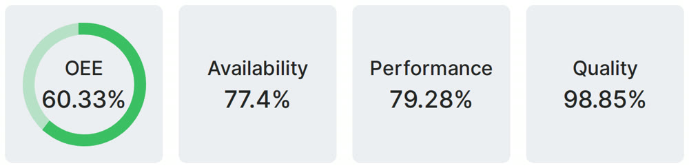
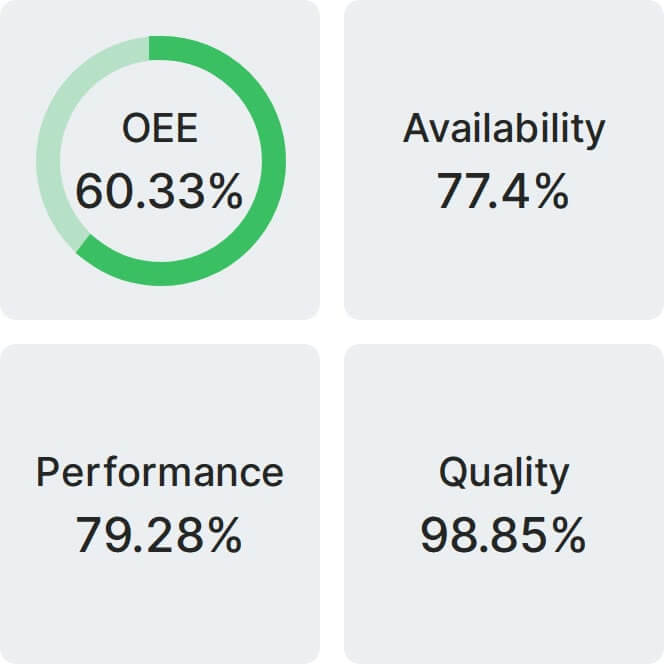
Real Fabrico tiles, sample data.